SB140S Ver la hoja de datos (PDF) - Shenzhen Luguang Electronic Technology Co., Ltd
Número de pieza
componentes Descripción
Fabricante
SB140S Datasheet PDF : 2 Pages
| |||
SB120S-SB1A0S
Schottky Barrier Rectifiers
VOLTAGE RANGE: 20 --- 100 V
CURRENT: 1.0 A
Features
◇
◇
◇
◇
◇
xxxx
◇
Metal-Semiconductor junction with guard ring
Epitaxial construction
Low forward voltage drop,low switching losses
High surge capability
For use in low voltage,high frequency inverters free
wheeling,and polarity protection applications
The plastic material carries U/L recognition 94V-0
A-405
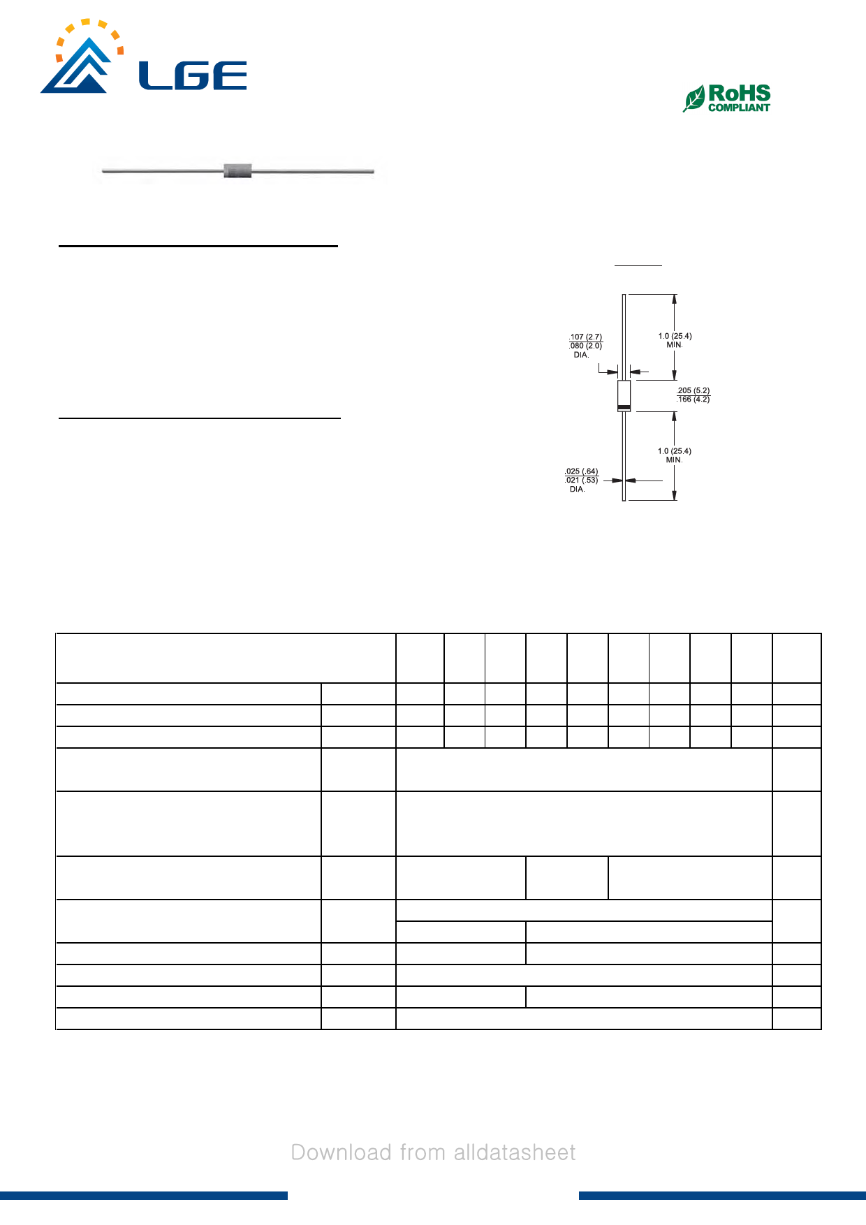
Mechanical Data
◇ Case:JEDEC A-405,molded plastic
◇ Terminals: Axial lead ,solderable per
MIL- STD-202,Method 208
◇ Polarity: Color band denotes cathode
◇ Weight: 0.008 ounces,0.23 grams
◇ Mounting position: Any
Dimensions in inches and (millimeters)
MAXIMUM RATINGS AND ELECTRICAL CHARACTERISTICS
Ratings at 25℃ ambient temperature unless otherwise specified.
Single phase,half wave,60 Hz,resistive or inductive load. For capacitive load,derate by 20%.
Maximum recurrent peak reverse voltage
Maximum RMS voltage
Maximum DC blocking voltage
Maximum average forward rectified current
9.5mm lead length,
(see fig.1)
VRRM
VRMS
VDC
IF(AV)
Peak forward surge current
8.3ms single half-sine-wave
superimposed on rated load
@TJ=125℃
IFSM
Maximum instantaneous forward voltage
@ 1.0A
VF
Maximum reverse current
@TA=25℃
at rated DC blocking voltage @TA=100℃
IR
Typical junction capacitance (Note1)
CJ
Typical thermal resistance (Note2)
RθJA
Operating junction temperature range
TJ
Storage temperature range
TSTG
NOTE: 1. Measured at 1.0MHz and applied reverse voltage of 4.0V DC.
2.Thermalresistance junction to ambient
SB
120S
SB
130S
SB SB SB SB
140S 150S 160S 170S
SB
180S
SB
190S
SB
1A0S
UNITS
20 30 40 50 60 70 80 90 100 V
14 21 28 35 42 49 56 63 70 V
20 30 40 50 60 70 80 90 100 V
1.0
A
40.0
A
0.5
10.0
110
- 55 --- + 125
0.7
0.85
0.5
5.0
80
50
- 55 --- + 150
- 55 --- + 150
V
mA
pF
℃/W
℃
℃
Revision:20170701-P1
http://www.lgesemi.com
mail:lge@lgesemi.com
Share Link: 