ART45U120 Ver la hoja de datos (PDF) - Unspecified
Número de pieza
componentes Descripción
Fabricante
ART45U120 Datasheet PDF : 2 Pages
| |||
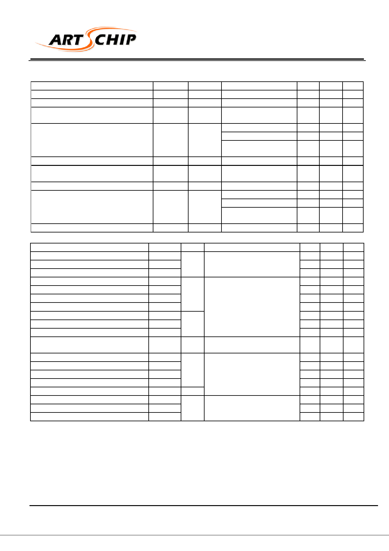
ART45U120(1GBT1200)
INSULATED GATE BIPOLAR TRANSISTOR
ELECTRICAL CHARACTERISTICS (Tj =25 °C)
Parameter
Symbol Units
Test Conditions
Collector-to-Emitter Breakdown Voltage
Emitter-to-Collector Breakdown Voltage
Breakdown Voltage Temp.Coefficient
Collector-to-Emitter Saturation
Voltage
(see figure 2,5)
V(BR)CES
V(BR)ECS
∆V(BR)CES/
∆TJ
VCE(ON)
Gate Threshold Voltage
Threshold Voltage Temp.Coefficient
Forward Transconductance
Zero Gate Voltage Collector
Current
VGE(th)
∆V(GE)th/
∆TJ
g (fe)
ICES
Gate-to-Emitter Leakage Current
IGES
V
V
V/˚C
V
V
mV/˚C
S
µA
nA
VGE = 0V, IC = 250µA
VGE = 0V, IC = 1A
VGE = 0V, IC = 2 mA
VGE = 15V, IC = 24A
VGE = 15V, IC = 45A
VGE = 15V, IC = 24A
TJ =150˚C
VGE=VCE, IC =250 µA
VGE=VCE, IC =2mA
VCE = 100V, IC = 24 A
VCE = 1200V, VGE =0V
VCE = 10V, VGE =0V
VCE = 1200V, VGE =0V
TJ =150˚C
VGS = ±20V
SWITCHING CHARACTERISTICS (Tj =25 °C)
Parameter
Symbol Units
Test Conditions
Total Gate Charge (turn on)
Gate-to-Emitter Charge (turn on)
Gate-to-Collector Charge (turn on)
Turn-On Delay Time
Rise Time
Turn-Off Delay Time
Fall Time
Turn-On Switching Loss
Turn-Off Switching Loss
Total Switching Loss
Short Circuit Withstand Time
Turn-On Delay Time
Rise Time
Turn-Off Delay Time
Fall Time
Total Switching Loss
Input Capacitance
Output Capacitance
Reverse Transfer Capacitance
Qg
Qge
Qgc
td(on)
tr
td(off)
tf
Eon
Eoff
EtS
tSC
td(on)
tr
td(off)
tf
EtS
CISS
COSS
CRSS
VGE = 15V,VCC = 400V,
nC IC =40A
See Figure 8
ns VCC =960V, IC =240A
VGE = 15V RG=24 Ω
Energy losses include «tail»
mJ See Figure 9,10,14
µS
Vcc=720V, TJ=125˚C
VGE=15V RG=5,0Ω
TJ =150˚C
ns VCC =960V, IC =24A
VGE = 15V RG=24 Ω
Energy losses include «tail»
mJ See Figure 10,11,14
VGE = 0V,VCC = 30V,
pF
f = 1.0MHz
See Figure 7
NOTES:
1 Repetitive rating; VGE =20V, pulse width limited by max junction temperature.(Fig.13b)
2 VCC=80%(VCES), L= 10 µH, VGE = 15V, RG=5,0 Ω,(Fig.13a)
3 Pulse width ≤80 µs, duty factor ≤0,1%.
4 Pulse width 5,0µs single short.
Min Typ. Max
1200 -
-
18
-
-
-
0,9
-
-
2,6 3,5
-
3,1
-
-
2,6
-
3,0
-
6,0
- -10 -
13 19
-
-
- 250
-
- 2,0
-
- 5000
±100
Min Typ. Max
- 180 270
-
25 38
-
70 110
-
36
-
-
27
-
- 200 300
- 130 190
- 1,21
- 2,25
- 3,46 4,1
10
-
-
-
35
-
-
29
-
- 380 -
- 280 -
- 7,80 -
- 2800 -
- 140 -
-
53
-
www.artschip.com
2
Share Link: 