LA17000M データシートの表示(PDF) - SANYO -> Panasonic
部品番号
コンポーネント説明
メーカー
LA17000M Datasheet PDF : 54 Pages
| |||
LA17000M
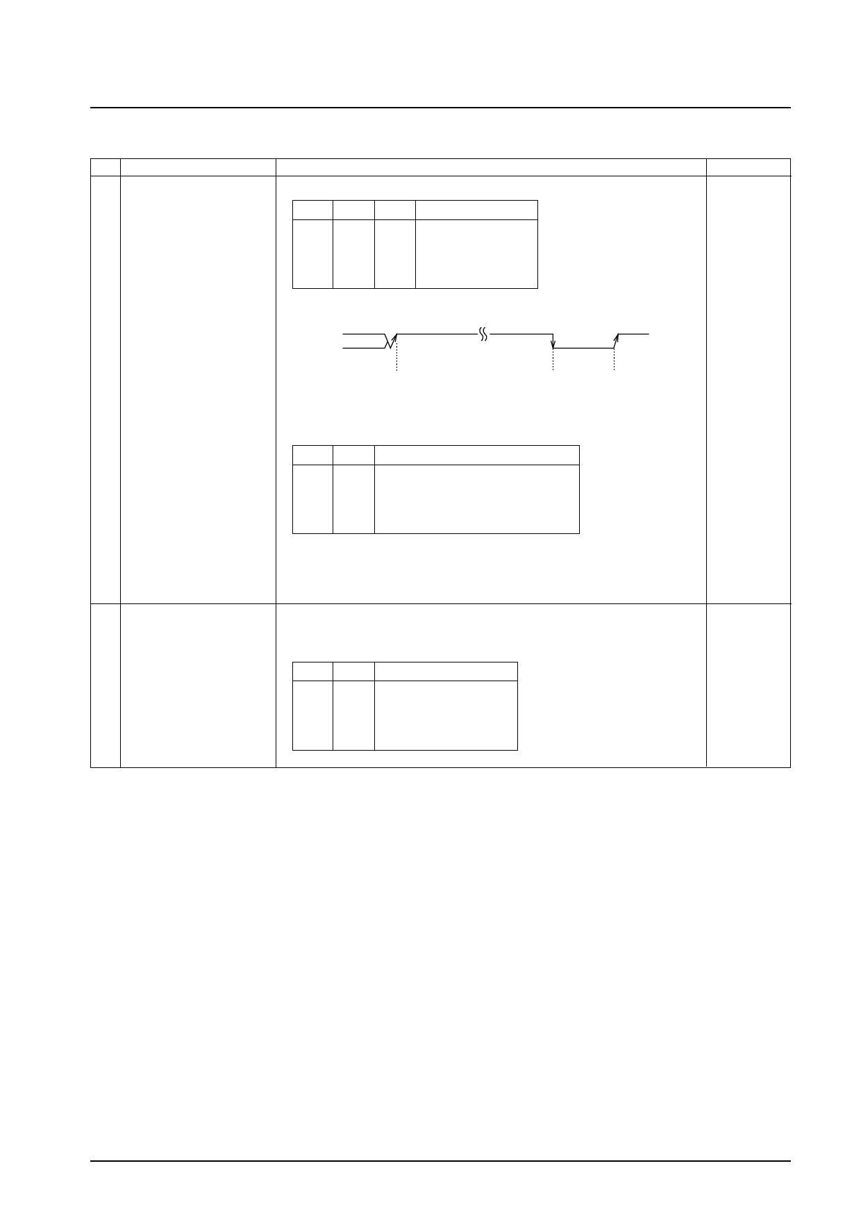
Continued from preceding page.
No.
Control block/Data
Description
DO, I/O-5 pin control data • This data determines the output on the DO pin and the I/O-5 pin.
ULD
DT0, DT1
IL0, IL1
ULD DT1 DT0
DO pin
0
0
0 Low when unlocked
0
0
1 end-AD
0
1
0 end-UC
0
1
1 IN (*1)
end-AD: End of conversion by the A/D converter
end-UC: End of conversion by the general-purpose counter
Related data
I/O-1
I/O-2
DO
(4)
Start
End
CE:Hi
(I-1 changes)
*1
IL1
0
0
1
1
IL
IN
0 Open
1 I-1 (pin status)
0 I-2 (pin status)
1 If I-1 changes, DO goes low. (Note)
A13315
* However, if the I/O-1 and I/O-2 pins are specified as output ports, these pins
are open.
Note: Cannot be used when X’tal OSC is set to STOP. (DO does not change.)
[When the reference divider data: R3 = R2 = R1 = 1 and R0 = 0]
A/D converter control data
• A/D converter conversion start data.
ADS = 1: A/D conversion reset and start
0: A/D conversion reset
(5)
ADS
ADI0
ADI1
1
1
0
0
ADI0
1
0
1
0
AD input pin
Stopped
ADC0
Not usable
Not usable
Continued on next page.
No. 6522-20/54
Share Link: 