MAX6635 データシートの表示(PDF) - Maxim Integrated
部品番号
コンポーネント説明
メーカー
MAX6635
Maxim Integrated
MAX6635 Datasheet PDF : 16 Pages
| |||
MAX6633/MAX6634/
MAX6635
12-Bit Plus Sign Temperature Sensors
with SMBus/I2C-Compatible Serial Interface
and the serial interface. Enter shutdown by programming
the shutdown bit of the configuration register high. While
in shutdown, the temperature register retains the last
conversion result and can be read at any time. The ADC
is turned off, reducing the device current draw to 30µA
(max). The outputs of ALERT and OVERT are latched
upon entering shutdown, and the fault queue is held in
reset. After coming out of shutdown, the temperature
register continues to read the last converted temperature,
until the next conversion result is available.
Thermal Considerations
The MAX6633/MAX6634/MAX6635 supply current is typ-
ically 200µA when the serial interface is inactive. When
used to drive high-impedance loads, the devices dissipate
negligible power; therefore, the die temperature is essen-
tially the same as the package temperature. The key to
accurate temperature monitoring is good thermal contact
between the MAX6633/MAX6634/MAX6635 package and
the monitored device or circuit. Heat flows in and out of
plastic packages primarily through the leads. Short, wide
copper traces leading to the temperature monitor ensure
that heat transfers quickly and reliably. The rise in die
temperature due to self-heating is given by the following
formula:
∆TJ = PDISSIPATION x θJA
where PDISSIPATION is the power dissipated by the
MAX6633/MAX6634/MAX6635, and θJA is the package's
thermal resistance.
The typical thermal resistance is 170°C/W for the 8-pin
SO package. To limit the effects of self-heating, mini-
mize the output currents. For example, if the MAX6634/
MAX6635 sink 4mA with the maximum ALERT VL specifi-
cation of 0.8V, an additional 3.2mW of power is dissipated
within the IC. This corresponds to a 0.54°C rise in the die
temperature.
Applications Information
Figure 10 shows the MAX6634 used as a simple ther-
mostat to control a heating element. Figure 11 shows the
MAX6635 used as a temperature-triggered fan controller.
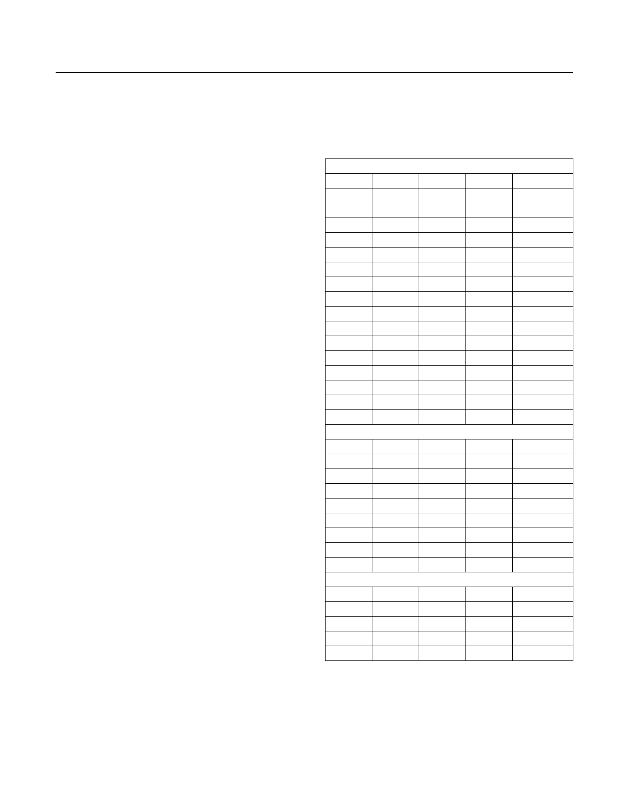
Table 1. Address Selection
A3
GND
GND
GND
GND
GND
GND
GND
GND
VCC
VCC
VCC
VCC
VCC
VCC
VCC
VCC
A2
GND
GND
GND
GND
VCC
VCC
VCC
VCC
GND
GND
GND
GND
VCC
VCC
VCC
VCC
A2
GND
GND
GND
GND
VCC
VCC
VCC
VCC
MAX6633
A1
GND
GND
VCC
VCC
GND
GND
VCC
VCC
GND
GND
VCC
VCC
GND
GND
VCC
VCC
MAX6634
A1
GND
GND
VCC
VCC
GND
GND
VCC
VCC
MAX6635
A1
GND
GND
VCC
VCC
A0
GND
VCC
GND
VCC
GND
VCC
GND
VCC
GND
VCC
GND
VCC
GND
VCC
GND
VCC
A0
GND
VCC
GND
VCC
GND
VCC
GND
VCC
A0
GND
VCC
GND
VCC
ADDRESS
1000 000
1000 001
1000 010
1000 011
1000 100
1000 101
1000 110
1000 111
1001 000
1001 001
1001 010
1001 011
1001 100
1001 101
1001 110
1001 111
ADDRESS
1001 000
1001 001
1001 010
1001 011
1001 100
1001 101
1001 110
1001 111
ADDRESS
1001 000
1001 001
1001 010
1001 011
www.maximintegrated.com
Maxim Integrated │ 12
Share Link: 