MAX3873A(2003) データシートの表示(PDF) - Maxim Integrated
部品番号
コンポーネント説明
メーカー
MAX3873A
(Rev.:2003)
(Rev.:2003)
Maxim Integrated
MAX3873A Datasheet PDF : 12 Pages
| |||
Low-Power, Compact 2.5Gbps or 2.7Gbps
Clock-Recovery and Data-Retiming IC
The loop filter output controls the on-chip LC VCO run-
ning at either 2.488GHz or 2.67GHz. The VCO provides
low phase noise and is trimmed to the correct
frequency. Clock jitter generation is typically 2psRMS
within a jitter band of 12kHz to 20MHz.
Loss-of-Lock Monitor
A loss-of-lock (LOL) monitor is incorporated in the
MAX3873A to indicate either a loss of frequency lock or
the absence of incoming data. Under loss-of-lock con-
ditions, LOL may momentarily assert high due to noise.
Design Procedure
Setting the Loop Filter
The MAX3873A is designed for both regenerator and
receiver applications. Its fully integrated PLL is a classic
second-order feedback system, with a loop bandwidth
(JBW) below 2.0MHz. The external capacitor, CF, can be
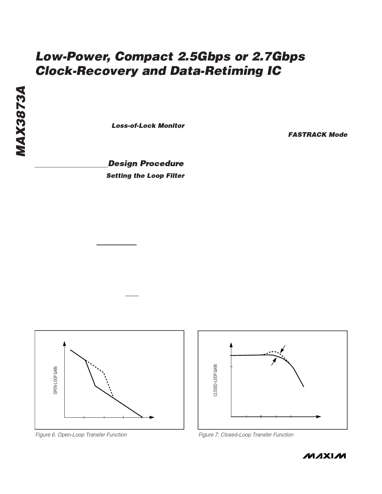
adjusted to set the loop damping. Figures 6 and 7 show
the open-loop and closed-loop transfer functions. The
PLL zero frequency, fZ, is a function of external capacitor
CF and can be approximated according to:
fz
=
1
2π (3000Ω) CF
with CF expressed in F.
For an overdamped system, the jitter peaking (JP) of a
second-order system can be approximated by:
JP
= 20log 1 +
fz
JBW
For example, using CF = 2000pF results in jitter peaking
of 0.2dB. Reducing CF below 500pF might result in PLL
instability. The recommended value is CF = 0.022µF to
guarantee a maximum jitter peaking of less than 0.1dB.
CF must be a low TC, high-quality capacitor of type X7R
or better.
FASTRACK Mode
The MAX3873A has a PLL fast-track (FASTRACK) mode
to decrease locking time in switched data applications.
In applications where the input data is switched from one
source to another, there is a brief period in which there is
no valid data input to the MAX3873A. In the absence of
input data, the PLL phase slowly drifts from the ideal
position. By enabling FASTRACK during reacquisition,
the time required to regain phase alignment is reduced.
This is accomplished by increasing the loop bandwidth
by approximately 50%.
The bandwidth of the MAX3873A is also linearly depen-
dent upon the transition density of the input data. By using
a preamble of 1200 bits of a 1–0 pattern during switching,
the loop bandwidth is increased by a factor of approxi-
mately 2 (Figure 3). Thus, by using a 1–0 pattern pream-
ble and enabling FASTRACK, the PLL bandwidth is
increased by a factor of approximately 3, resulting in the
fastest possible reacquisition of phase lock.
FASTRACK increases the rate at which the MAX3873A
acquires the proper phase, assuming that the VCO is
already running at the proper frequency. On startup con-
ditions, however, the VCO frequency is significantly differ-
ent from the input data, and the time required to lock to
the incoming data is increased to approximately 1.0ms.
HO(j2πf) (dB)
CF = 0.022µF
fZ = 2.4kHz
CF = 2000pF
fZ = 26kHz
H(j2πf) (dB)
0
-3
CF = 2000pF
CF = 0.022µF
1
10
100
Figure 6. Open-Loop Transfer Function
f (kHz)
1000
1
10 100 1000
Figure 7. Closed-Loop Transfer Function
8 _______________________________________________________________________________________
f (kHz)
Share Link: 