M48T212Y-70MH1TR(2000) гГЗгГЉгВњгВЈгГЉгГИгБЃи°®з§ЇпЉИPDFпЉЙ - STMicroelectronics
йГ®еУБзХ™еПЈ
гВ≥гГ≥гГЭгГЉгГНгГ≥гГИи™ђжШО
гГ°гГЉгВЂгГЉ
M48T212Y-70MH1TR Datasheet PDF : 23 Pages
| |||
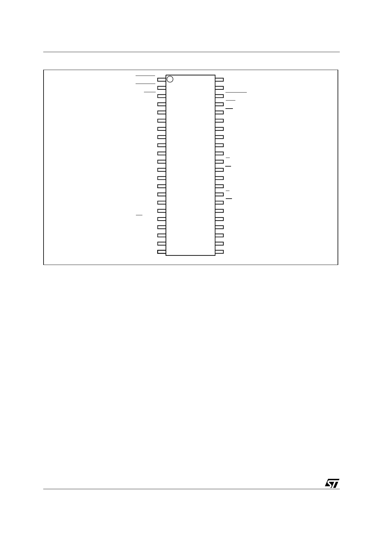
M48T212Y, M48T212V
Table 7B. DC Characteristics for M48T212Y
(TA = 0 to 70°C; VCC = 4.5V to 5.5V)
Symbol
Parameter
Test Condition
Min
Typ
Max
Unit
ILI (1,2) Input Leakage Current
0V вЙ§ VIN вЙ§ VCC
±1
µA
ILO (1) Output Leakage Current
0V вЙ§ VOUT вЙ§ VCC
±1
µA
ICC Supply Current
Outputs open
8
15
mA
ICC1 Supply Current (Standby) TTL
E = VIH
5
mA
ICC2 Supply Current (Standby) CMOS
E = VCC вАУ0.2
3
mA
Battery Current OSC ON
IBAT
Battery Current OSC OFF
575
800
nA
100
nA
VIL
Input Low Voltage
вАУ0.3
0.8
V
VIH Input High Voltage
2.2
VCC + 0.3 V
Output Low Voltage
VOL
Output Low Voltage (open drain) (3)
IOL = 2.1mA
IOL = 10mA
0.4
V
0.4
V
VOH Output High Voltage
IOH = вАУ1.0mA
2.4
V
VOHB (4) VOH Battery Back-up
IOUT2 = вАУ1.0¬µA
2.0
3.6
V
IOUT1 (5) VOUT Current (Active)
VOUT1 > VCC вАУ0.3
100
mA
IOUT2 VOUT Current (Battery Back-up)
VOUT2 > VBAT вАУ0.3
100
µA
VPFD Power-fail Deselect Voltage
4.2
4.35
4.5
V
VSO Battery Back-up Switchover Voltage
3.0
V
VBAT Battery Voltage
3.0
V
Note: 1. Outputs deselected.
2. RSTIN1 and RSTIN2 internally pulled-up to VCC through 100KвД¶ resistor. WDI internally pulled-down to VSS through 100KвД¶ resistor.
3. For IRQ/FT & RST pins (Open Drain).
4. Conditioned outputs (E1CON - E2CON) can only sustain CMOS leakage currents in the battery back-up mode. Higher leakage cur-
rents will reduce battery life.
5. External SRAM must match TIMEKEE PER Controller chip VCC specification.
The M48T212Y/V also has its own Power-Fail De-
tect circuit. This control circuitry constantly moni-
tors the supply voltage for an out of tolerance
condition. When VCC is out of tolerance, the circuit
write protects the TIMEKEEPER register data and
external SRAM, providing data security in the
midst of unpredictable system operation. As VCC
falls, the control circuitry automatically switches to
the battery, maintaining data and clock operation
until valid power is restored.
Address Decoding
The M48T212Y/V accommodates 4 address lines
(A3-A0) which allow access to the sixteen bytes of
the TIMEKEEPER clock registers. All TIMEKEEP-
ER registers reside in the controller chip itself. All
TIMEKEEPER registers are accessed by enabling
E (Chip Enable).
6/23
Share Link: 