EL2150CS-T7 データシートの表示(PDF) - Intersil
部品番号
コンポーネント説明
メーカー
EL2150CS-T7 Datasheet PDF : 19 Pages
| |||
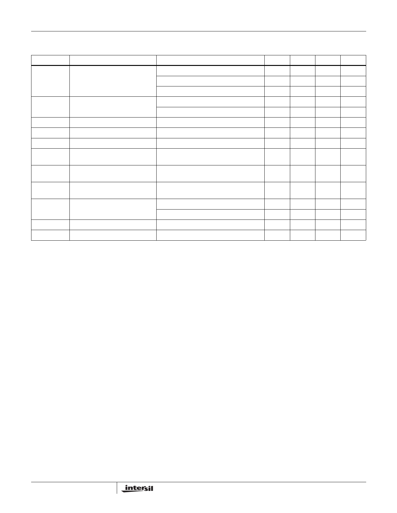
EL2150, EL2157
DC Electrical Specifications VS = +5V, GND = 0V, TA = 25°C, VCM = 1.5V, VOUT = 1.5V, VCLAMP = +5V, VENABLE = +5V, unless
otherwise specified. (Note 1) (Continued)
PARAMETER
DESCRIPTION
CONDITIONS
MIN
TYP
MAX
UNIT
VON
IOUT
IOUT,OFF
VIH-EN
VIL-EN
IIH-EN
Negative Output Voltage Swing
Output Current (Note 2)
Output Current, Disabled
ENABLE pin Voltage for Power Up
VS = 12V, AV = 1, RL = 150Ω to 0V
VS = ±5V, AV = 1, RL = 1kΩ to 0V
VS = ±5V, AV = 1, RL = 150Ω to 0V
VS = ±5V, AV = 1, RL = 10Ω to 0V
VS = ±5V, AV = 1, RL = 50Ω to 0V
VENABLE = 0.5V
Relative to GND pin
ENABLE pin Voltage for Shut Down Relative to GND pin
ENABLE pin Input Current-High
(Note 3)
VS = VCLAMP = 12V, VENABLE = 12V
5.5
8
mV
-4.0
V
-3.7
-3.4
V
±75
±100
mA
±60
mA
0
20
µA
2.0
V
0.5
V
340
410
µA
IIL-EN
ENABLE pin Input Current-Low
(Note 3)
VS = VCLAMP = 12V, VENABLE = 0.5V
0
1
µA
VOR-CL
Voltage Clamp Operating Range
(Note 4)
Relative to GND pin
1.2
VOP
V
VACC-CL
IIH-CL
IIL-CL
CLAMP Accuracy
CLAMP pin Input Current - High
CLAMP pin Input Current - Low
VIN = 4V, RL = 1kΩ to GND
VCLAMP = 1.5V and 3.5V
VS = VCLAMP = 12V
VS = 12V, VCLAMP = 1.2V
-250
100
250
mV
12
25
µA
-20
-15
µA
NOTES:
1. CLAMP pin and ENABLE pin specifications apply only to the EL2157.
2. Internal short circuit protection circuitry has been built into the EL2150/EL2157. See the Applications section.
3. If the disable feature is not desired, tie the ENABLE pin to the VS pin, or apply a logic high level to the ENABLE pin.
4. The maximum output voltage that can be clamped is limited to the maximum positive output Voltage, or VOP. Applying a voltage higher than
VOP inactivates the clamp. If the clamp feature is not desired, either tie the CLAMP pin to the VS pin, or simply let the CLAMP pin float.
4
Share Link: 