GA100TS120UPBF データシートの表示(PDF) - Vishay Semiconductors
部品番号
コンポーネント説明
メーカー
GA100TS120UPBF Datasheet PDF : 10 Pages
| |||
GA100TS120UPbF
"Half-Bridge" IGBT INT-A-PAK Vishay High Power Products
(Ultrafast Speed IGBT), 100 A
THERMAL AND MECHANICAL SPECIFICATIONS
PARAMETER
SYMBOL
TEST CONDITIONS
Thermal resistance, junction to case
IGBT
Diode
RthJC
Thermal resistance, case to sink per module
Mounting torque
case to heatsink
case to terminal 1, 2 and 3
RthCS
For screws M5 x 0.8
Weight of module
TYP.
-
-
0.1
-
-
200
MAX.
0.24
0.35
-
4.0
3.0
-
UNITS
°C/W
Nm
g
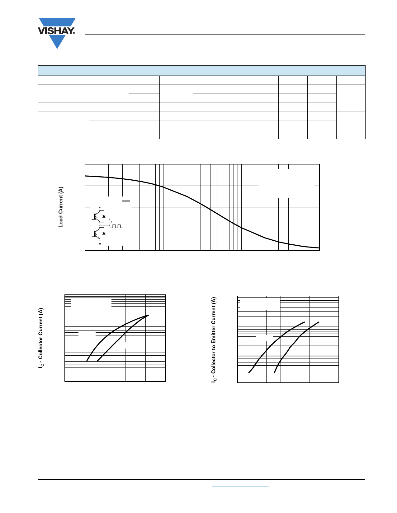
100
75
Square wave:
50
60 % of rated
voltage
25
0
0.1
Ideal diodes
1000
VGE = 15 V
500 µs pulse width
100
125 °C
10
25 °C
Duty cycle: 50 %
TJ = 125 °C
Tsink = 90 °C
Gate drive as specified
Power dissipation = 170 W
1
10
100
f - Frequency (kHz)
Fig. 1 - Typical Load Current vs. Frequency
(Load Current = IRMS of Fundamental)
1000
VGE = 20 V
500 µs pulse width
100
125 °C
25 °C
10
1
0.5
1.0
1.5
2.0
2.5
3.0
VCE - Collector to Emitter Voltage (V)
Fig. 2 - Typical Output Characteristics
1
4.0 4.5 5.0 5.5 6.0 6.5 7.0 7.5
VGE - Gate to Emitter Voltage (V)
Fig. 3 - Typical Transfer Characteristics
Document Number: 94428
Revision: 04-May-10
For technical questions, contact: indmodules@vishay.com
www.vishay.com
3
Share Link: 