L484D1 データシートの表示(PDF) - STMicroelectronics
部品番号
コンポーネント説明
メーカー
L484D1 Datasheet PDF : 11 Pages
| |||
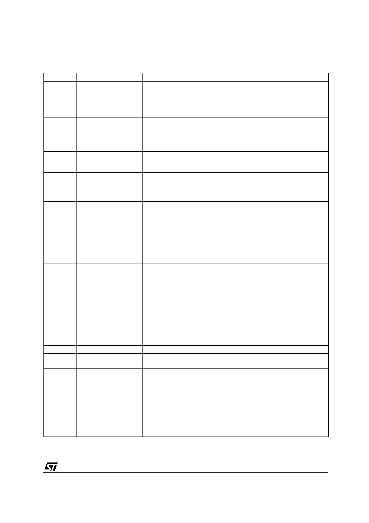
L484
PIN FUNCTIONS (refer to fig. 2)
N°
Name
Function
1
CURRENT SENSING Connection for Coil Current Limitation. The current is measured on the
INPUT
sense resistor RSENS and divided on R1/R2. The current limitation value is
given by :
ISENS
=
R1 + R2
RSENS R2
2
PICKUP INPUT
Magnetic Pickup Signal Input. This pin sets the dwell time, i.e. the max
negative pickup voltage value starting from which the device can drive the
current into the coil. The real dwell time will be a function of the dwell
control logic. Increasing the resistor R11 the maximum conduction time
increases. The max input current foreseen is 2mA.
3
PERMANENT
A capacitor C1 connected between this pin and ground sets the delay of the
CONDUCT.
permanent conduction protection in the coil current. Using a 50nF capacitor
PROTECTION TIMER the typical desaturation time delay for the protection is 75ms.
4
PERMANENT CONDUCT. A low level on this input (max 0.7V) disables the protection, irrespective of
PROTECTION INHIBIT the state of pin 3. If the protection is used this pin must be left open.
5
RPM OUTPUT
Open collector output signal which is at a low level when the final darlington
is in ON status. The current is internally limited at 10mA.
6
DWELL TIME ADJUST At high motor rotation speeds, i.e. when the peak value of the magnetic
pick-up signal exceedes 6V using R12 = 100KΩ, this pin may be used to
vary the dwell ratio. Adding a resistor in series Ra between this pin and pin
11 the desaturation time is reduced. It is therefore possible to use this pin to
adapt the L484 to various pickup types. The maximum value of the resistor
Ra is 200KΩ.
7
DWELL CONTROL A capacitor C2 connected between this pin and ground sets the timing for
TIMER
the dwell control. The recommended value is 100nF. The resistors Rb/Rc
provide an hysteresis to confirm ON state and avoid spurious sparks.
8
ZERO CROSSING Zero cross detector input of the magnetic pickup signal for the ignition
INPUT
actuation. At high motor rotation speeds, the external resistor R12 may be
used to vary the desaturation time ratio, to adapt the L484 to various
signal waveforms of time magnetic pick-up. Reducing the resistor value the
dwell time increases. Typically the range of values for resistor R12 is from
50KΩ to 150KΩ..
9
POWER-ON INPUT A low level on this pin forces the external darlington into conduction
particularly useful in anti knock system. This function is particularly useful in
antiknock system because provides a spark time delay. Anyway the current
limitation, the permanent conduction protection and the dump protection
are operating even when pin 9 is at a low level. If this function is not used it
must be left open.
10
SIGNAL GROUND This pin must be connected to ground.
11
POWER SUPPLY Supply Voltage Input. A 7V (typ) zener is present at the input. The external
resistor R9 limits the current through the zener for higher supply voltages.
12
DUMP PROTECTION The device is protected against the load dump. In load dump condition an
internal circuit, based on a zener diode and a darlington transistor,
switches off the external darlington and short circuits the supply.
By means of the external divider R8/R9 the protection threshold can be
changed and is given as first approximation by:
VDth
=
8.5
R8 + R9
R9
+
5
⋅
10−4
R8
(the resistor R9 value must be higher than 4KΩ).
* this function is particularly useful in antiknock systeme because provides a spark time delay. anyway the current limitation, the pemanent con
duction protection and the dump protection are operating even when pin 9 is at a low level.
3/11
Share Link: 