LTC2953I データシートの表示(PDF) - Linear Technology
部品番号
コンポーネント説明
メーカー
LTC2953I Datasheet PDF : 20 Pages
| |||
LTC2953
TYPICAL APPLICATIONS
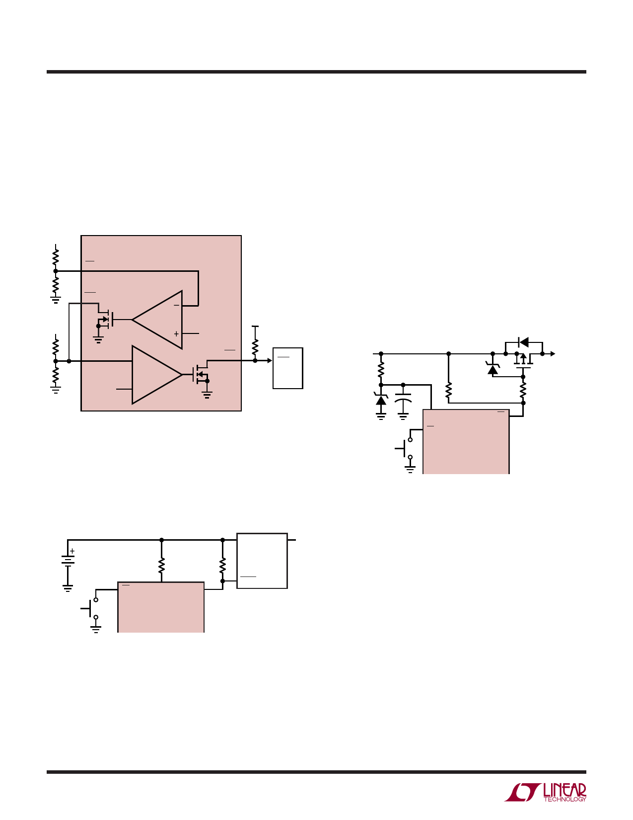
Dual Supply Monitor with μP Reset
Operation with Supply Transients over 40V
The circuit of Figure 22 monitors two supplies and provides
a μP reset. When either the ⎯P⎯F⎯I or the VM input voltage
falls below its threshold (0.5V), the ⎯R⎯S⎯T output is asserted
low. ⎯R⎯S⎯T remains low for 200ms after both inputs rise
above 0.5V. The low leakage ⎯P⎯F⎯O output allows for large
valued external resistors.
V2
LTC2953
PFI
PFO
V1
VM
–
0.5V
+
0.5V
RST
RST
μP
2953 F22
Figure 22. Dual Supply Monitor with μP Reset
Reverse Battery Protection
The application circuit of Figure 24 operates from a 24V
nominal supply, but can withstand supply transients as
high as 40V.
The high voltage ⎯E⎯N output of the LTC2953-2 has an ab-
solute maximum rating of 50V, which makes it suitable for
driving the gate of the external power PFET. The external
30V Zener diode (Z1) and the 10k current limiting resistor
(RZ) protect the VIN supply pin of the LTC2953-2. Note
that under normal 24V operation, the external Zener diode
does not conduct any current. The voltage drop across
RZ should be kept below 1V. Z2 should have a breakdown
voltage smaller than the PFET’s gate-to-source breakdown
voltage.
24V NOMINAL,
40V TRANSIENTS
RZ
10k
30V
Z1
BZX84C30
ON/OFF
1μF
50V
VIN
PB
10V
Z2
BZX84C10
R5
100k
EN
LTC2953-2
FDS4685
Si2319DS
NDS9407
R9
100k
50V
ABS MAX
To protect the LTC2953 from a reverse battery connec-
tion, place a 1k resistor (R8) in series with the VIN pin.
See Figure 23.
8.4V
ON/OFF
R8
R5
1k
910k
PB
VIN
EN
LTC2953-1
VIN
VOUT
LT1761
SHDN
2953 F23
2953 F24
Figure 24. Operation with 40V Supply Transients
Power Path Controller with Low Battery Detect
The application in Figure 25 uses the push button to
completely disconnect the load from the battery. If the
battery voltage falls below the user specified threshold, the
push button is prevented from turning on system power
(asserting the enable output).
Figure 23. Reverse Battery Protection Using R8
2953f
18
Share Link: 