MC145106 データシートの表示(PDF) - Motorola => Freescale
部品番号
コンポーネント説明
メーカー
MC145106 Datasheet PDF : 8 Pages
| |||
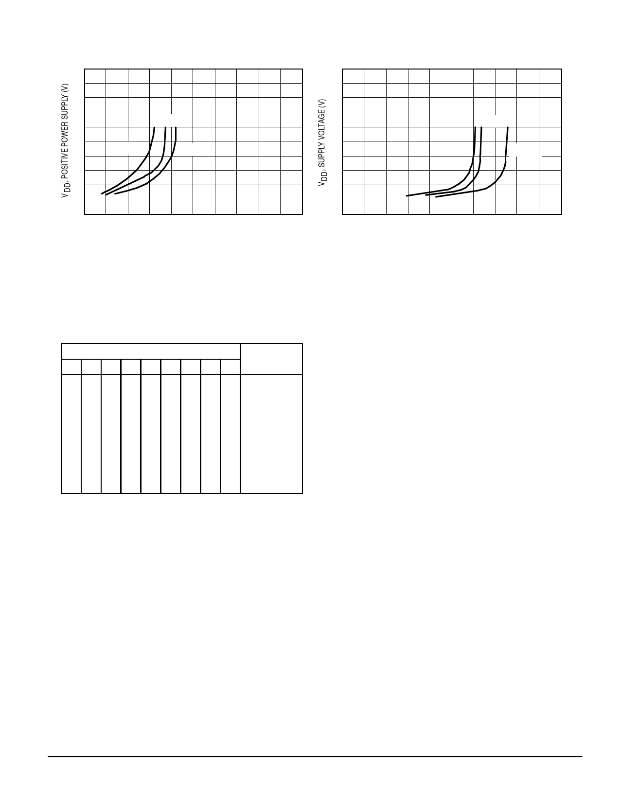
TYPICAL CHARACTERISTICS*
25
25
20
+ 25°C
15
+ 85°C
10
– 40°C
20
+ 25°C
15
+ 85°C
– 40°C
10
5.0
5.0
0
0
0
10
20
30
40
50
0
10
20
30
40
50
fin, MAXIMUM FREQUENCY (MHz)
OSCin, MAXIMUM FREQUENCY (MHz)
Figure 1. Maximum Divider Input Frequency
versus Supply Voltage
Figure 2. Maximum Oscillator Input Frequency
versus Supply Voltage
* Data labelled “Typ” is not to be used for design purposes but is intended as an indication of the IC’s potential performance.
TRUTH TABLE
Selection
P8 P7 P6 P5 P4 P3 P2 P1 P0 Divide by N
000000000
2*
000000001
3*
000000010
2
000000011
3
000000100
4
011111111
255
111111111
511
1: Voltage level = VDD.
0: Voltage level = 0 or open circuit input.
* The binary setting of 00000000 and 00000001 on P8 to P0 results
in a 2 and 3 division which is not in the 2N – 1 sequence. When pin
is not connected the logic signal on that pin can be treated as a “0”.
PIN DESCRIPTIONS
P0 – P8
Programmable Inputs (PDIP — Pins 17 – 9; SOG — Pins
19, 17 – 14, 12 – 9)
Programmable divider inputs (binary).
fin
Frequency Input (PDIP, SOG — Pin 2)
Frequency input to programmable divider (derived from
VCO).
OSCin, OSCout
Oscillator Input and Oscillator Output (PDIP, SOG —
Pins 3, 4)
Oscillator/amplifier input and output terminals.
LD
Lock Detector (PDIP, SOG — Pin 8)
LD is high when loop is locked, pulses low when out–of–
lock.
φDetout (PDIP, SOG — Pin 7)
Signal for control of external VCO, output high when fin/N is
less than the reference frequency; output low when fin/N is
greater than the reference frequency. Reference frequency is
the divided down oscillator — input frequency typically 5.0 or
10 kHz.
NOTE
Phase Detector Gain = VDD/4π.
FS
Reference Oscillator Frequency Division Select (PDIP,
SOG — Pin 6)
When using 10.24 MHz OSC frequency, this control selects
10 kHz, a “0” selects 5.0 kHz.
÷ 2out (PDIP, SOG — Pin 5)
Reference OSC frequency divided by 2 output; when using
10.24 MHz OSC frequency, this output is 5.12 MHz for fre-
quency tripling applications.
VDD
Positive Power Supply (PDIP, SOG — Pin 1)
VSS
Ground (PDIP — Pin 18, SOG — Pin 20)
MOTOROLA
MC145106
4
Share Link: 