NCV7381(2012) гГЗгГЉгВњгВЈгГЉгГИгБЃи°®з§ЇпЉИPDFпЉЙ - ON Semiconductor
йГ®еУБзХ™еПЈ
гВ≥гГ≥гГЭгГЉгГНгГ≥гГИи™ђжШО
гГ°гГЉгВЂгГЉ
NCV7381 Datasheet PDF : 23 Pages
| |||
NCV7381
FUNCTIONAL DESCRIPTION
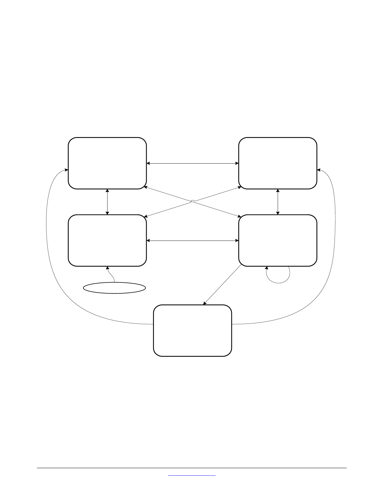
Operating Modes
NCV7381 can switch between several operating modes
depicted in Figure 3. In Normal and ReceiveвИТonly modes,
the chip interconnects a FlexRay communication controller
with the bus medium for fullвИТspeed communication. These
two modes are also referred to as normalвИТpower modes.
In Standby and Sleep modes, the communication is
suspended and the power consumption is substantially
reduced. A wakeup on the bus or through a locally
monitored signal on pin WAKE can be detected and signaled
to the host. GoвИТtoвИТsleep mode is a temporary mode ensuring
correct transition between any mode and the Sleep mode. All
three modes вАУ Standby, Sleep and GoвИТtoвИТsleep вАУ are referred
to as lowвИТpower modes.
The operating mode selected is a function of the host
signals STBN and EN, the state of the supply voltages and
the wakeup detection. As long as all three supplies (VBAT,
VCC, VIO) remain above their respective underвИТvoltage
detection levels, the logical control by EN and STBN pins
shown in Figure 3 applies. Influence of the powerвИТsupplies
and of the wakeup detection on the operating modes is
described in subsequent paragraphs.
STBN=H
EN=H
Normal Mode
Transmitter: on
Receiver: on
INH: High
Power cons.: normal
STBN=H
EN=H
STBN=H
EN=H
STBN=L
EN=L
Standby Mode
STBN=H
EN=H
STBN=L
EN=L
Transmitter: off
Receiver: wakeupвИТdetection
INH: High
Power cons.: low
STBN=L
EN=L
ReceiveвИТonly Mode
STBN=H
EN=L
Transmitter: off
Receiver: on
INH: High
Power cons.: normal
STBN=H
EN=L STBN=H
EN=L
STBN=L
STBN=L
EN=H
EN=H
GoвИТtoвИТsleep Mode
STBN=H
EN=L
STBN=L
EN=H
Transmitter: off
Receiver: wakeupвИТdetection
INH: High
Power cons.: low
PowerвИТup
Sleep Mode
STBN=L, EN=H
for <dGoвИТtoвИТSleep
STBN=L, EN=H
for >dGoвИТtoвИТSleep
Transmitter: off
Receiver: wakeupвИТdetection
INH: floating
Power cons.: low
Figure 3. Operating Modes and their Control by the STBN and EN Pins
http://onsemi.com
4
Share Link: 