S6B0759 データシートの表示(PDF) - Samsung
部品番号
コンポーネント説明
メーカー
S6B0759 Datasheet PDF : 68 Pages
| |||
S6B0759
PRELIMINARY SPEC. VER. 1.2
81 COM / 128 SEG DRIVER & CONTROLLER FOR STN LCD
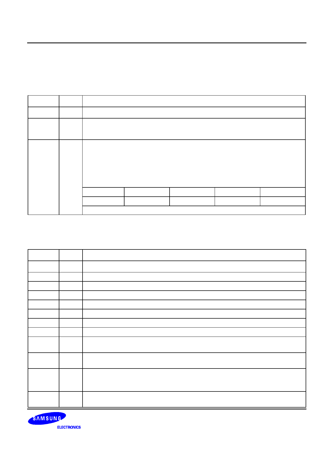
PIN DESCRIPTION
POWER SUPPLY
Table 2. Power Supply Pins
Name
I/O
Description
VDD
VSS1
VSS2
Supply Power supply
Supply Ground VSS1 and VSS2 must be shorted to External wire.
LCD driver supplies voltages
The voltage determined by LCD pixel is impedance converted by an operational amplifier
for application.
V0
Voltages should have the following relationship;
V1
V0 ≥ V1 ≥ V2 ≥ V3 ≥ V4 ≥ VSS
V2
I/O When the internal power circuit is active, these voltages are generated as following table
V3
according to the state of LCD bias.
V4
LCD bias
V1
V2
V3
V4
1/N bias
(N-1) / N x V0 (N-2) / N x V0
(2/N) x V0
(1/N) x V0
NOTE: N = 4 to 11
LCD DRIVER SUPPLY
Table 3. LCD Driver Supply Pins
Name
I/O
Description
C1-
C1+
C2-
C2+
C3+
C4+
C5+
VOUT
VCI
VR
REF
VEXT
O Capacitor 1 negative connection pin for voltage converter
O Capacitor 1 positive connection pin for voltage converter
O Capacitor 2 negative connection pin for voltage converter
O Capacitor 2 positive connection pin for voltage converter
O Capacitor 3 positive connection pin for voltage converter
O Capacitor 4 positive connection pin for voltage converter
O Capacitor 5 positive connection pin for voltage converter
I/O Voltage converter input / output pin
I
Voltage converter input voltage pin
Voltages should have the following relationship: VDD ≤ VCI ≤ V0
I
V0 voltage adjustment pin
It is valid only when on-chip resistors are not used (INTRS = "L")
Selects the external VREF voltage via VEXT pin
I − REF = "L": using the external VREF
− REF = "H": using the internal VREF
I
Externally input reference voltage (VREF) for the internal voltage regulator
It is valid only when REF is "L".
7
Share Link: 