MAX1617DBR2(2000) データシートの表示(PDF) - ON Semiconductor
部品番号
コンポーネント説明
メーカー
MAX1617DBR2
(Rev.:2000)
(Rev.:2000)
ON Semiconductor
MAX1617DBR2 Datasheet PDF : 12 Pages
| |||
MAX1617
DETAILED OPERATING DESCRIPTION
The MAX1617 acquires and converts temperature
information from two separate sources, both silicon junction
diodes, with a basic accuracy of ±1°C. One is located on the
MAX1617 die; the other is connected externally. The
external diode may be located on another IC die. The
analog–to–digital converter on the MAX1617 alternately
converts temperature data from the two sensors and stores
them separately in internal registers.
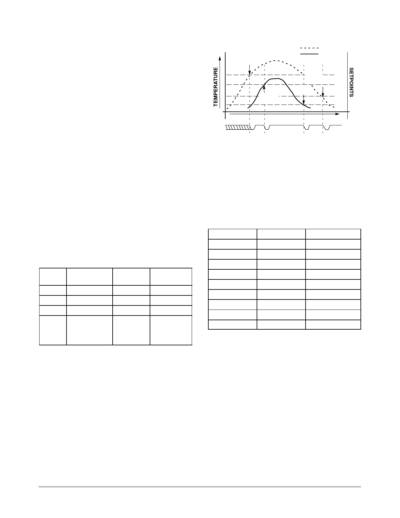
The system interface is a slave SMBus port with an
ALERT (SMBALERT) interrupt output. The interrupt is
triggered when one or more of four preset temperature
thresholds are tripped (see Figure 1). These four thresholds
are user–programmable via the SMBus port. Additionally,
the temperature data can be read at any time through the
SMBus port. Nine SMBus addresses are programmable for
the MAX1617, which allows for a multi–sensor
configuration. Also, there is low–power Standby mode
where temperature acquisition is suspended.
STANDBY MODE
The MAX1617 allows the host to put it into a low power
(IDD = 10 µA, max) Standby mode. In this mode, the A/D
converter is halted, and the temperature data registers are
frozen. The SMBus port operates normally. Standby mode
can be enabled with either the STBY input pin or the CHIP
STOP bit in the CONFIG register. The following table
summarizes this operation.
ASSERT
ALERT
ASSERT
ALERT
EXT_TEMP
INT_TEMP
EXT_HLIM
ASSERT
ALERT INT_HLIM
ASSERT
ALERT
EXT_LLIM
INT_LLIM
ALERT
TIME
Note: This diagram implies that the appropriate setpoint is moved,
temporarily, after each ALERT event to suppress re–assertion
of ALERT immediately after the ARA/de–assertion.
Figure 1. Temperature vs. Setpoint Event Generation
SMBus SLAVE ADDRESS
The two pins ADD1 and ADD0 are tri–state input pins
which determine the 7–bit SMBus slave address of the
MAX1617. The address is latched during POR.
Address Decode Table
ADD0
ADD1
SMBus Address
0
0
0011 000
0
open (3–state)
0011 001
Standby Mode Operation
STBY Chip Stop Bit One Shot?
0
Don’t Care Don’t Care
1
0
Don’t Care
1
1
No
1
1
Yes
Operating
Mode
Standby
Normal
Standby
Normal (1
Conversion
Only, then
Standby)
0
open (3–state)
open (3–state)
open (3–state)
1
1
1
1
0
open (3–state)
1
0
open (3–state)
1
0011 010
0101 001
0101 010
0101 011
1001 100
1001 101
1001 110
http://onsemi.com
6
Share Link: 