PTH04040W データシートの表示(PDF) - Artesyn Technologies
部品番号
コンポーネント説明
メーカー
PTH04040W Datasheet PDF : 4 Pages
| |||
PTH04040
3.3/5 Vin single output
DC-DC CONVERTERS POLA Non-isolated
For the most current data and application support visit www.artesyn.com/powergroup/products.htm
2
NEW Product
OUTPUT
POWER
(MAX.)
150 W
INPUT
VOLTAGE
2.95-5.5 Vdc
OUTPUT
VOLTAGE
0.8-2.5 Vdc
OUTPUT
CURRENT
(MIN.)
0A
OUTPUT
CURRENT
(MAX.) (7)
60 A
EFFICIENCY
(MAX.)
93%
REGULATION
LINE
LOAD
±5 mV
±5 mV
MODEL
NUMBER (9,10)
PTH04040W
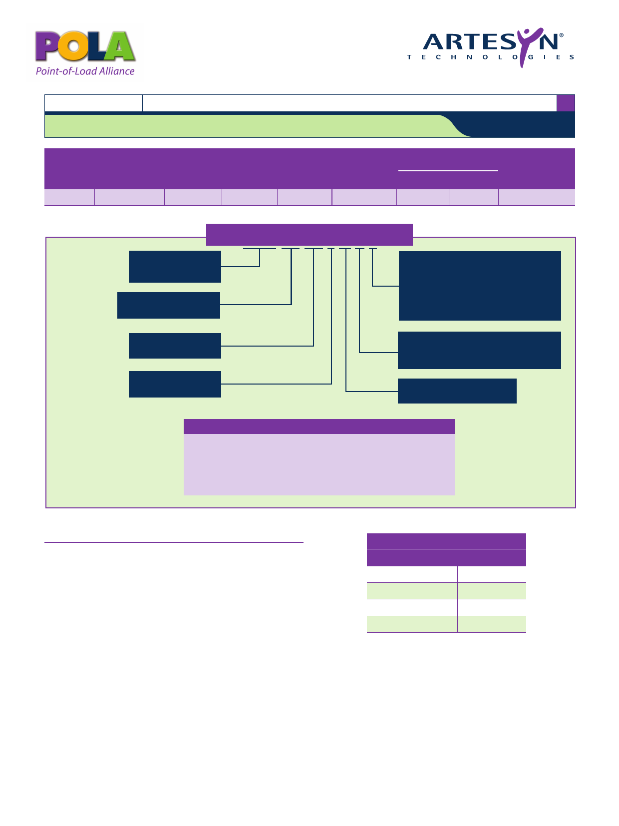
Part Number System with Options
Product Family
Point of Load Alliance
Compatible
Input Voltage
04 = 2.95 Vdc to 5.5 Vdc
Output Current
04 = 60 A
Mechanical Package
Always 0
PTH04040WAS
Mounting Option (9)
D = Horizontal Through-Hole (Matte Sn)
H = Horizontal Through-Hole (Sn/Pb)
S = Surface-Mount (63/37 Sn/Pb
pin solder material)
Z = Surface-Mount (96.5/3.0/0.5 Sn/Ag/Cu
pin solder material)
Pin Option
A = Through-Hole Std. Pin Length (0.140”)
A = Surface-Mount Tin/Lead Solder Ball
Output Voltage Code
W = Wide
Output Voltage Adjustment of the PTH04040W Series
The ultra-wide output voltage trim range offers major advantages to users who
select the PTH04040W. It is no longer necessary to purchase a variety of
modules in order to cover different output voltages. The output voltage can be
trimmed in a range of 0.8 Vdc to 2.5 Vdc. When the PTH04040W converter
leaves the factory the output has been adjusted to the default voltage of 0.8 V.
Notes
1 The set-point voltage tolerance is affected by the tolerance and stability
of RSET. The stated limit is unconditionally met if RSET has a tolerance of
1% with 100 ppm/ºC or better temperature stability.
2 This control pin has an internal pull-up to Vin nominal. If it is left open-
circuit the module will operate when input power is applied. A small low-
leakage (<100 nA) MOSFET is recommend for control. For further
information, consult Application Note 192.
3 A 1000 µF input capacitor is required for proper operation. The capacitor
must be rated for a minimum of 400 mA rms of ripple current.
4 This is with a 1 A/µs loadstep, 50 to 100% Iomax. Co = 660 µF.
5 The minimum input voltage is 2.95 V or 1.34 x Vo, whichever is greater.
6 These are default voltages. They may be adjusted using the ‘UVLO Prog.’
control input. Consult Application Note 192 for further details.
7 See Figures 1 and 2 for safe operating curves. All power pins must be
used.
8 A small low-leakage (<100 nA) MOSFET is recommended to control this
pin. The opencircuit voltage is less than 1 Vdc.
9 To order Pb-free (RoHS compatible) surface-mount parts replace the
mounting option ‘S’ with ‘Z’, e.g. PTH04040WAZ. To order Pb-free
(RoHS compatible) through-hole parts replace the mounting option ‘H’
with ‘D’, e.g. PTH04040WAD.
10 NOTICE: Some models do not support all options. Please contact your
local Artesyn representative or use the on-line model number search tool at
http://www.artesyn.com/powergroup/products.htm to find a suitable
alternative.
EFFICIENCY TABLE (Io = 45A) Vin = 5 V
OUTPUT VOLTAGE EFFICIENCY
Vo = 2.5 V
93%
Vo = 1.8 V
90%
Vo = 1.5 V
88%
Vo = 1.2 V
86%
File Name: pth04040.pdf Rev: 27 Jun 2006
Share Link: 