CXA2040 データシートの表示(PDF) - Sony Semiconductor
部品番号
コンポーネント説明
メーカー
CXA2040 Datasheet PDF : 22 Pages
| |||
CXA2040Q
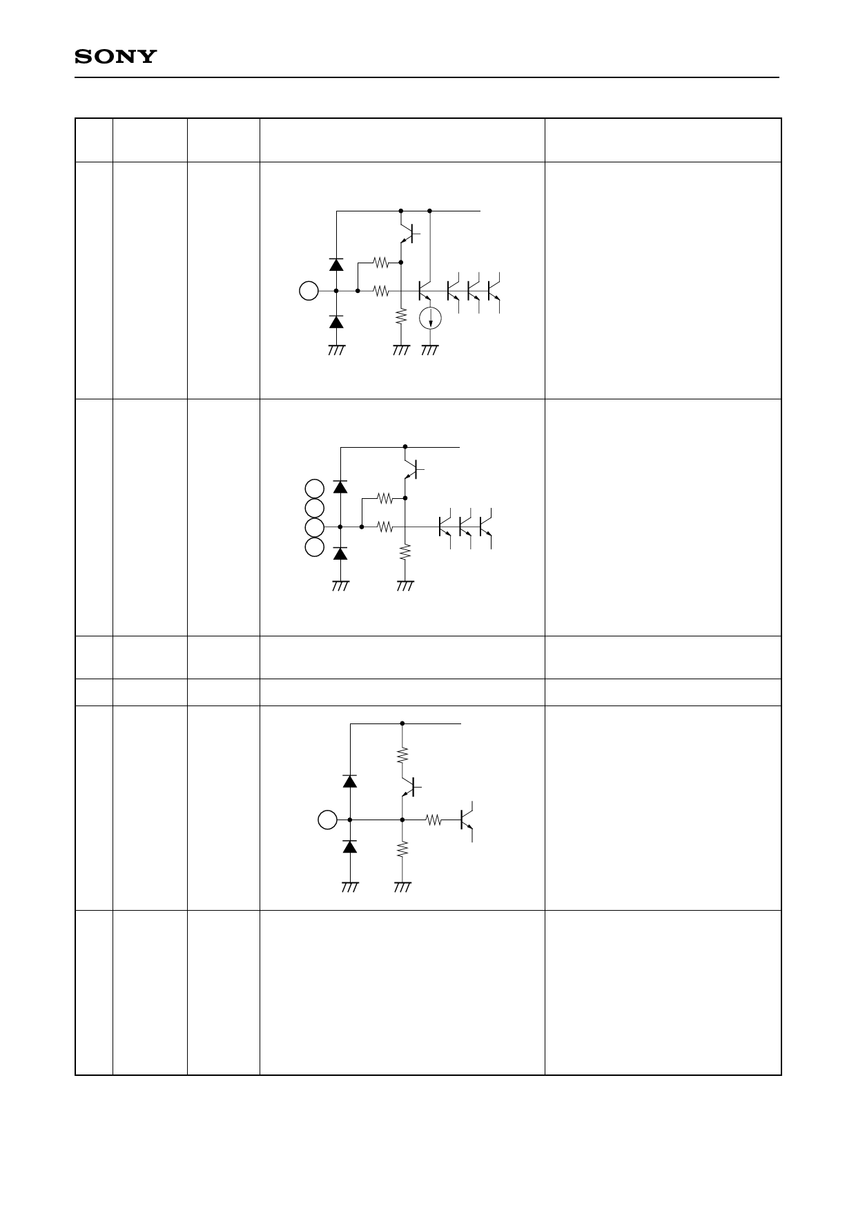
Pin
No.
Symbol Pin voltage
Equivalent circuit
VCC
23 CV1
4.5V
20k
147
23
28k
Description
Composite video signal input.
Biased to approximately 4.5V.
Input the input signal through
capacitor. Connect protective
resistor of 220Ω between this pin
and the capacitor.
The composite video signal input
to CV1 is also taken into the
"SYNC DETECT circuit" of which
SYNC is existed or not.
25 CV2
27 CV3
29 CV4
31 CV5
4.5V
VCC
25
20k
27
147
29
31
28k
Composite video signal input.
Biased to approximately 4.5V.
Input the input signals through
capacitors. Connect protective
resistor of 220Ω between these
pins and the capacitors.
26 VCC
30 GND
9.0V∗1
0.0V∗1
32 BIAS
4.5V
2
8
10
12
14 NC
16
18
24
28
VCC
1.2k
22.5k
32
20k
Power supply.
Apply 9.0V.
GND.
4.5V bias.
Attach a decoupling capacitor
between this pin and GND.
This pin cannot be used as an
external power supply.
–5–
NC (not connected).
Connect to GND.
If these NC pins are not connected
to GND, the cross talk and other
desired values indicated in the
Electrical Characteristics cannot
be obtained.
∗1 Applied externally.
Share Link: 