AD5247 データシートの表示(PDF) - Analog Devices
部品番号
コンポーネント説明
メーカー
AD5247 Datasheet PDF : 20 Pages
| |||
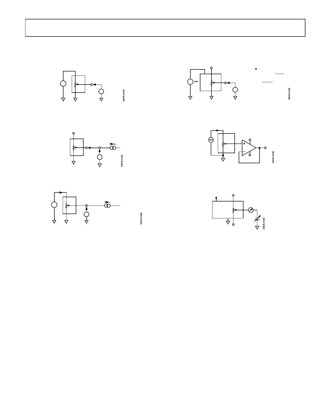
TEST CIRCUITS
Figure 25 to Figure 30 define the test conditions used in the
product Specification tables.
DUT
A
V+
W
B
V+ = VDD
1LSB = V+/2N
VMS
Figure 25. Test Circuit for Potentiometer Divider
Nonlinearity Error (INL, DNL)
NO CONNECT
DUT
A
W
B
IW
VMS
Figure 26. Test Circuit for Resistor Position Nonlinearity Error
(Rheostat Operation; R-INL, R-DNL)
VMS2
DUT
A
W
B
IW = VDD / RNOMINAL
VW
VMS1 RW = [VMS1 – VMS2]/ IW
Figure 27. Test Circuit for Wiper Resistance
AD5247
VA
DUT
VDD A
V+
W
B
( ) V+= VDD 10%
PSRR (dB) = 20 LOG
∆V MS
∆V DD
PSS (%/%) = ∆VMS%
∆V DD%
VMS
Figure 28. Test Circuit for Power Supply Sensitivity (PSS, PSSR)
DUT
A
+15V
VIN
W
B
OP27
VOUT
–15V
Figure 29. Test Circuit for Gain vs. Frequency
NC
DUT
VDD
A
W
GND B
ICM
VCM
NC
Figure 30. Test Circuit for Common-Mode Leakage Current
Rev. 0 | Page 11 of 20
Share Link: 