MC68000FN8 データシートの表示(PDF) - Motorola => Freescale
部品番号
コンポーネント説明
メーカー
MC68000FN8 Datasheet PDF : 26 Pages
| |||
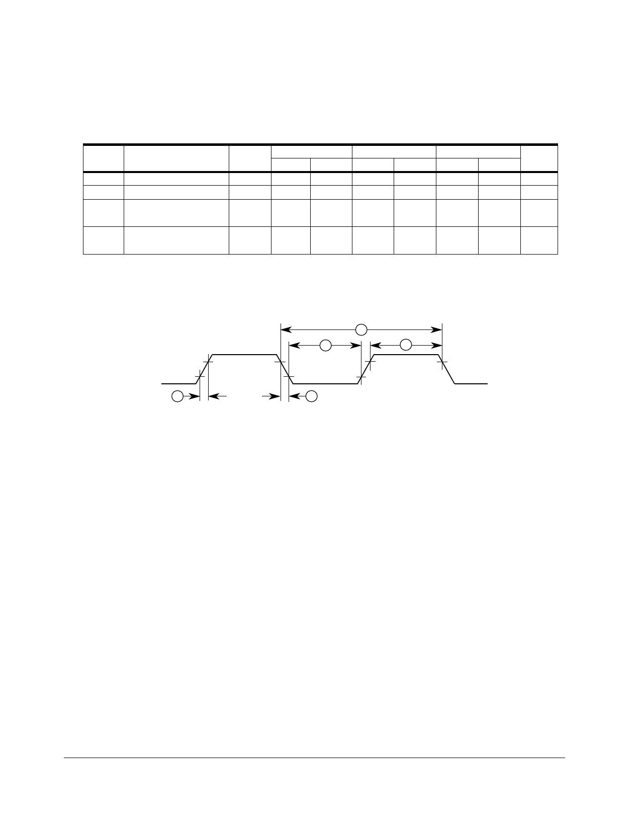
6.0 MC68SEC000 AC ELECTRICAL SPECIFICATIONS — CLOCK
TIMING (See Figure 2)
Add the following table and Figure 8 to Section 10.9 on page 10-9.
NUM.
1
2,3
4,5
CHARACTERISTIC
Frequency of Operation
Cycle time
Clock Pulse Width
Clock Rise and Fall Times
SYMBOL
f
tcyc
tCL
tCH
tCr
tCf
10MHz
MIN
MAX
0
10.0
100
—
45
—
45
—
—
10
—
10
16MHz
min
max
0
16.7
60
—
27
—
27
—
—
5
—
5
20MHz
min
max UNIT
0
20.0 MHz
50
—
ns
21
—
ns
21
—
—
4
ns
—
4
Applies to 3.3V and 5V.
2.0 V
0.8 V
4
1
2
3
5
NOTE: Timing measurements are referenced to and from a low voltage of 0.8 V and a
high voltage of 2.0 V, unless otherwise noted. The voltage swing through this
range should start outside and pass through the range such that the rise or
fall will be linear between 0.8 V and 2.0 V.
Figure 8. MC68SEC000 Clock Input Timing Diagram
11
M68000 USER’S MANUAL ADDENDUM
MOTOROLA
Share Link: 