M34282M2 데이터 시트보기 (PDF) - MITSUBISHI ELECTRIC
부품명
상세내역
제조사
M34282M2 Datasheet PDF : 70 Pages
| |||
MITSUBISHI MICROCOMPUTERS
4282 Group
SINGLE-CHIP 4-BIT CMOS MICROCOMPUTER
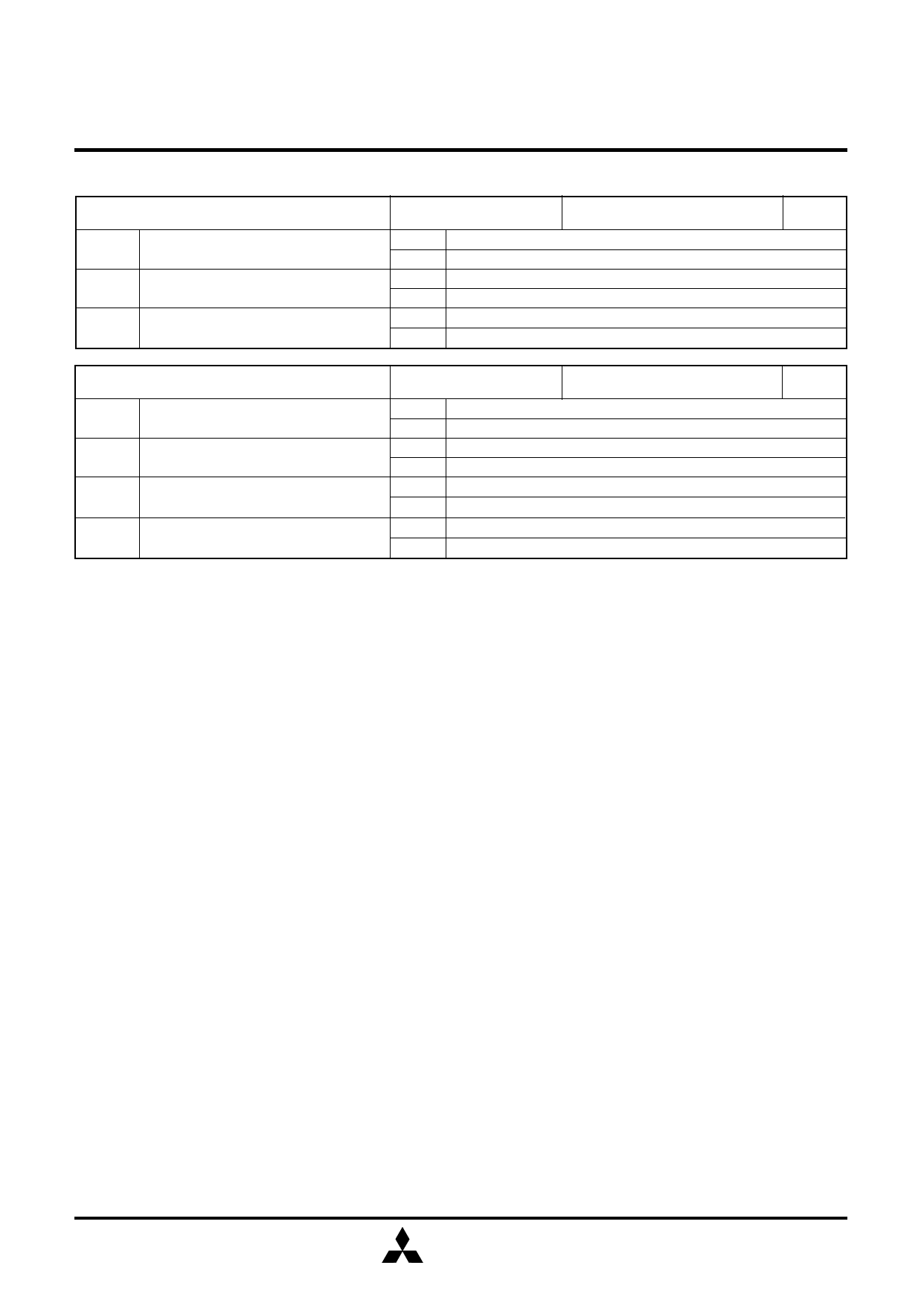
Table 4 Control registers related to timer
Timer control register V1
at reset : 0002
at RAM back-up : 0002
W
V12 Carrier wave output auto-control bit
V11 Timer 1 count source selection bit
V10 Timer 1 control bit
0 Auto-control output by timer 1 is invalid
1 Auto-control output by timer 1 is valid
0 Carrier wave output (CARRY)
1 Bit 5 of watchdog timer (WDT)
0 Stop (Timer 1 state retained)
1 Operating
Timer control register V1
at reset : 00002
at RAM back-up : 00002
W
V13 Carrier wave “H” interval expansion bit
0 To expand “H” interval is invalid
1 To expand “H” interval is valid (when V22=1 selected)
0 Carrier wave generation function invalid
V12 Carrier wave generation function control bit
1 Carrier wave generation function valid
V11 Timer 2 count source selection bit
0 f(XIN)
1 f(XIN)/2
V10 Timer 2 control bit
0 Stop (Timer 2 state retained)
1 Operating
Note: “W” represents write enabled.
(1) Control registers related to timer
• Timer control register V1
Register V1 controls the timer 1 count source and auto-
control function of carrier wave output from port CARR by
timer 1. Set the contents of this register through register A
with the TV1A instruction.
• Timer control register V2
Register V2 controls the timer 2 count source and the carrier
wave generation function by timer. Set the contents of this
register through register A with the TV2A instruction.
(2) Precautions
Note the following for the use of timers.
• Count source
Stop timer 1 or timer 2 counting to change its count source.
• Watchdog timer
Be sure that the timing to execute the WRST instruction in
order to operate WDT efficiently.
• Writing to reload register R1
When writing data to reload register R1 while timer 1 is
operating, avoid a timing when timer 1 underflows.
• Timer 1 count operation
When the bit 5 of the watchdog timer (WDT) is selected as
the timer 1 count source, the error of maximum ± 256 µs
(at the minimum instruction execution time : 8 µs) is
generated from timer 1 start until timer 1 underflow. When
programming, be careful about this error.
• Stop of timer 2
Avoid a timing when timer 2 underflows to stop timer 2.
• Writing to reload register R2H
When writing data to reload register R2H while timer 2 is
operating, avoid a timing when timer underflows.
• Timer 2 carrier wave output function
When to expand “H” interval of carrier wave is valid, set “1”
or more to reload register R2H.
MITSUBISHI
12
ELECTRIC
Share Link: 