MAX3935(2002) 데이터 시트보기 (PDF) - Maxim Integrated
부품명
상세내역
제조사
MAX3935 Datasheet PDF : 14 Pages
| |||
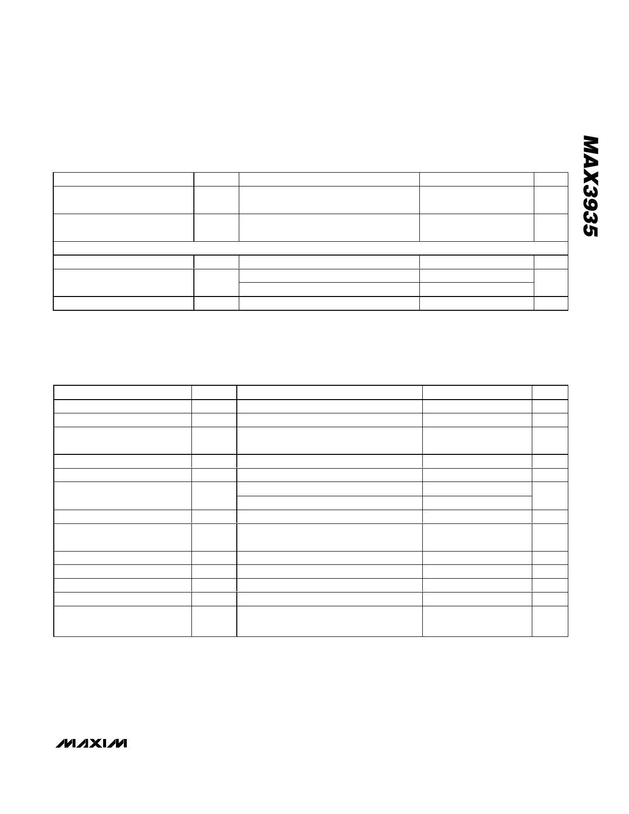
10.7Gbps EAM Driver
DC ELECTRICAL CHARACTERISTICS (continued)
(VEE = -4.9V to -5.5V ±6%, TA = -40°C to +85°C. Typical values are at VEE = -5.2V, IBIAS = 16.7mA, IMOD = 83.3mA, TA = +25°C,
unless otherwise noted.) (Note 1)
PARAMETER
SYMBOL
CONDITIONS
MIN TYP MAX UNITS
Differential Input Swing
(DC-Coupled)
VID
0.3
2.0
VP-P
Differential Input Swing
(AC-Coupled)
SIGNAL INPUT FOR VTT = -1.3V
Input Common Mode
Single-Ended Input
Differential Input Swing
VID
VICM
VIS
VID
At high
At low
0.3
1.6
VP-P
-1.225
-1.800
0.3
-1.3
-0.800
-1.375
2.0
V
V
VP-P
AC ELECTRICAL CHARACTERISTICS
(VEE = -4.9V to -5.5V ±6%, TA = -40°C to +85°C. Typical values are at VEE = -5.2V, IBIAS = 16.7mA, IMOD = 83.3mA, TA = +25°C,
unless otherwise noted.) (Notes 1, 4, 5)
PARAMETER
Input Data Rates
Input Return Loss
Modulation Current-Setting
Range
Modulation Current-Setting Error
Modulation Sensing Resistor
Modulation Current Temperature
Stability
Modulation Off-Current
Output Back Termination
Resistor
Output Edge Speed
Setup/Hold-Time
Pulse-Width Adjustment Range
Pulse-Width Stability
Pulse-Width Control Input
Range
SYMBOL
RLIN
IMOD
RMOD
tR, tF
tSU, tHD
CONDITIONS
NRZ (Note 2)
f ≤ 15GHz (Notes 2, 6)
IMOD defined in Figure 3 (Note 7)
TA = +25°C (Note 9)
IMOD = 100mA (Note 2)
IMOD = 20mA
MODSET ≤ (VEE + 0.4V)
ZL = 50Ω, 20% to 80% (Note 3)
Figure 2 (Notes 2, 3)
ZL = 50Ω, at 10Gbps (Notes 2, 3)
PWC+ and PWC- open (Notes 2, 3)
For PWC+ and PWC-
MIN
20
-10
2.7
-550
63.8
25
-6
VEE
TYP MAX UNITS
10.7
Gbps
15
dB
100
mA
3.0
-200
+10
3.3
+550
%
Ω
ppm/°C
0.1
mA
75.0 86.3
Ω
34
ps
ps
±60
ps
+6
ps
VEE + VEE +
1.0
2.0
V
_______________________________________________________________________________________ 3
Share Link: 