TA2123AF 데이터 시트보기 (PDF) - Toshiba
부품명
상세내역
제조사
TA2123AF Datasheet PDF : 20 Pages
| |||
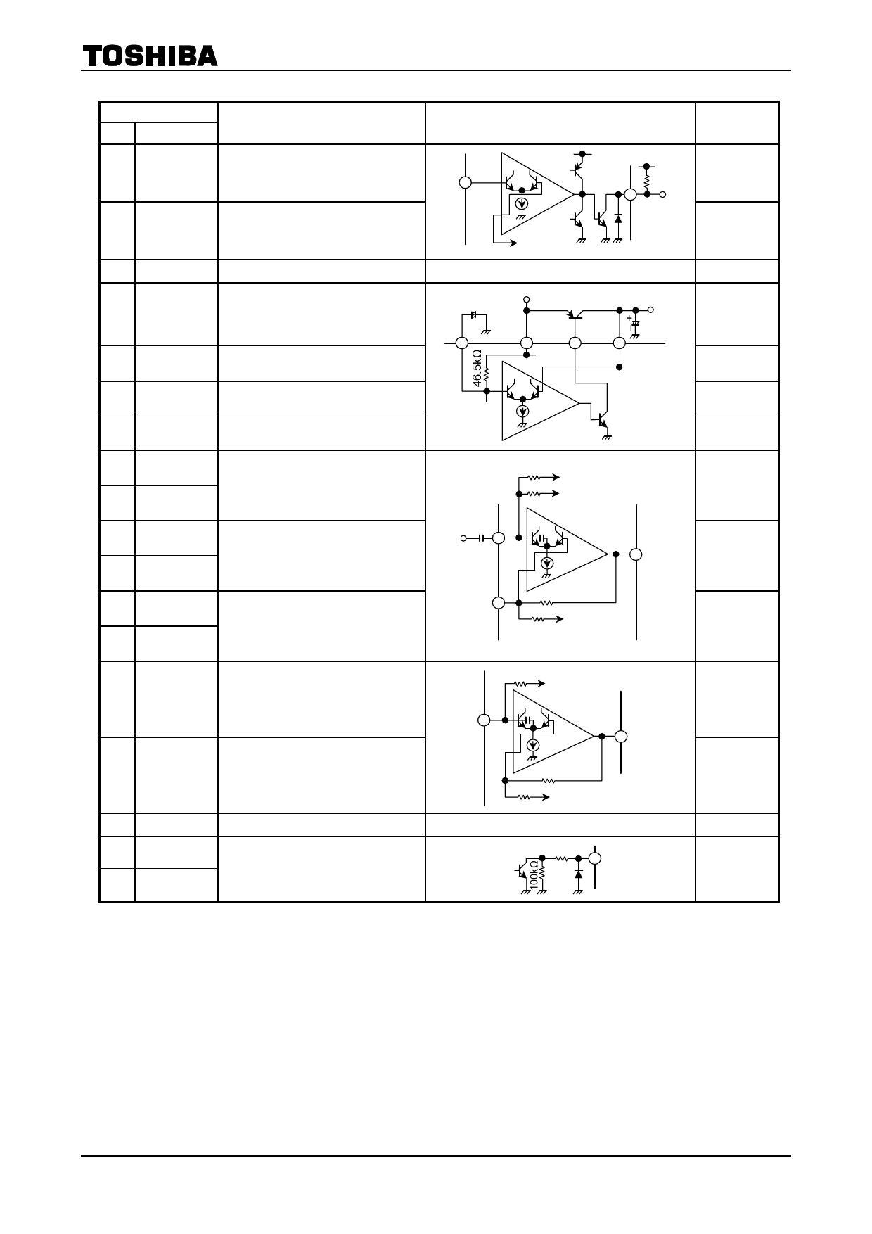
Terminal
No.
Name
Function
15 AMS DET
Input of AMS comparator circuit
40 AMS OUT
16 GND
17 RF OUT
18 BASE
19 VCC
24 RF IN
20 OUTA
22 OUTB
26 PW NFB
29 PW NFA
27 PW INB
28 PW INA
Output of AMS comparator circuit
High level: Rectangular pulse
Low level: “H”
—
Output of ripple filter
・Ripple filter circuit supplies
internal circuit except power
drive stage with power source
Base biasing terminal of transistor
for ripple filter
—
Ripple filter terminal
Output of power amplifier
NF of power amplifier
Input of power amplifier
(this terminal also has function of
an ADD amplifier input.)
21 OUTC
Output of center amplifier
32 PW INC
Input of center amplifier
23 PW GND
25 EQB
30 EQA
Power GND for power drive stage
Equalizer circuit (this circuit
synchronizes with the BST SW)
・Input impedance
: 1.9Ω (typ.)
TA2123AF
Internal Circuit
15
40
VREF OUT
—
VCC
+-
24
19
18
RF OUT
17
20kΩ
20kΩ
to ADD amplifier
VREF OUT
28
20
30kΩ
29
2kΩ VREF OUT
Terminal
Voltage
(V)
0.73
—
0
1.22
0.5
1.3
1.23
0.56
0.73
0.73
20kΩ VREF OUT
32
21
30kΩ
2kΩ VREF OUT
—
1.8kΩ
30
0.56
0.73
0
—
4
2002-10-30
Share Link: 