PMBT3904 데이터 시트보기 (PDF) - Philips Electronics
부품명
상세내역
제조사
PMBT3904 Datasheet PDF : 8 Pages
| |||
Philips Semiconductors
NPN switching transistor
Product specification
PMBT3904
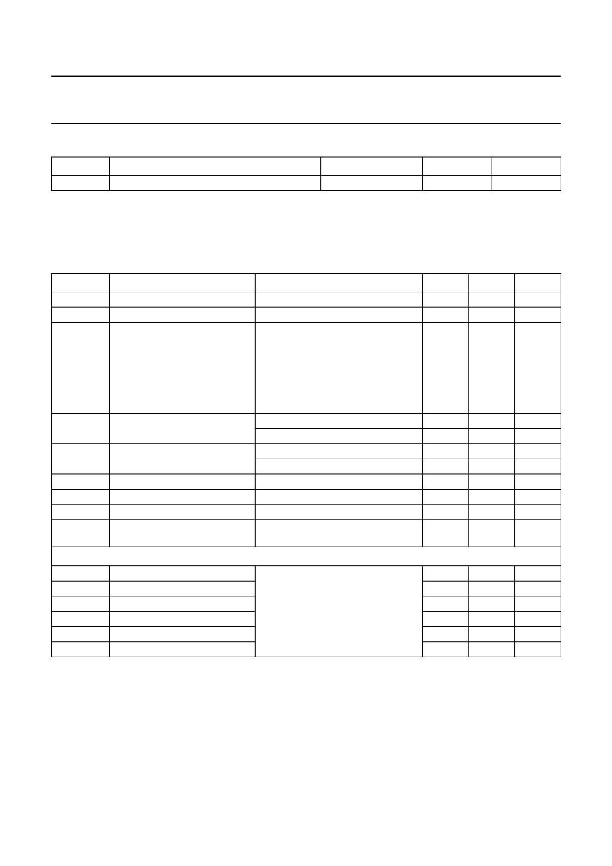
THERMAL CHARACTERISTICS
SYMBOL
PARAMETER
Rth j-a
thermal resistance from junction to ambient
Note
1. Transistor mounted on an FR4 printed-circuit board.
CONDITIONS
note 1
VALUE
500
UNIT
K/W
CHARACTERISTICS
Tamb = 25 °C unless otherwise specified.
SYMBOL
ICBO
IEBO
hFE
VCEsat
VBEsat
Cc
Ce
fT
F
PARAMETER
collector cut-off current
emitter cut-off current
DC current gain
collector-emitter saturation
voltage
base-emitter saturation voltage
collector capacitance
emitter capacitance
transition frequency
noise figure
CONDITIONS
MIN.
IE = 0; VCB = 30 V
−
IC = 0; VEB = 6 V
−
VCE = 1 V; note 1; Fig.2
IC = 0.1 mA
60
IC = 1 mA
80
IC = 10 mA
100
IC = 50 mA
60
IC = 100 mA
30
IC = 10 mA; IB = 1 mA
−
IC = 50 mA; IB = 5 mA
−
IC = 10 mA; IB = 1 mA
650
IC = 50 mA; IB = 5 mA
−
IE = ie = 0; VCB = 5 V; f = 1 MHz
−
IC = ic = 0; VBE = 500 mV; f = 1 MHz −
IC = 10 mA; VCE = 20 V; f = 100 MHz 300
IC = 100 µA; VCE = 5 V; RS = 1 kΩ; −
f = 10 Hz to 15.7 kHz
Switching times (between 10% and 90% levels); (see Fig.3)
ton
turn-on time
td
delay time
tr
rise time
toff
turn-off time
ts
storage time
tf
fall time
ICon = 10 mA; IBon = 1 mA;
−
IBoff = −1 mA
−
−
−
−
−
Note
1. Pulse test: tp ≤ 300 µs; δ ≤ 0.02.
MAX.
50
50
−
−
300
−
−
200
200
850
950
4
8
−
5
65
35
35
240
200
50
UNIT
nA
nA
mV
mV
mV
mV
pF
pF
MHz
dB
ns
ns
ns
ns
ns
ns
1999 Apr 27
3
Share Link: 