73K224L 데이터 시트보기 (PDF) - TDK Corporation
부품명
상세내역
제조사
73K224L Datasheet PDF : 32 Pages
| |||
73K224L
V.22bis/V.22/V.21/Bell 212A/Bell 103
Single-Chip Modem
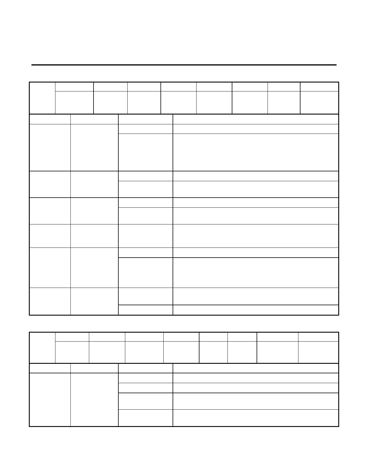
DETECT REGISTER (continued)
D7
D6
D5
D4
D3
D2
D1
D0
DR
RECEIVE
S1
RECEIVE UNSCR.
CARR.
ANSWER
CALL
SIGNAL
010
LEVEL
PATTERN DATA
MARK
DETECT
TONE
PROG.
QUALITY
INDICATOR DETECT
DETECT
DETECT
INDICATOR
BIT NO.
D2
D3
D4
D5
D6
D7
NAME
Answer Tone
Received
Carrier Detect
Unscrambled
Mark Detect
Receive Data
S1 Pattern
Detect
Receive Level
Indicator
CONDITION
0
1
0
1
0
1
0
1
0
1
DESCRIPTION
No answer tone detected.
In Call Init mode, indicates detection of 2225 Hz answer
tone in Bell mode (TR bit D0=0) or 2100 Hz if in CCITT
mode (TR bit D0=1). The device must be in originate mode
for detection of answer tone. Both answer tones are
detected in demod mode.
No carrier detected in the receive channel.
Indicated carrier has been detected in the received
channel.
No unscrambled mark.
Indicates detection of unscrambled marks in the received
data. Should be time qualified by software.
Continuously outputs the received data stream. This data is
the same as that output on the RXD pin, but it is not
disabled when RXD is tri-stated.
No S1 pattern being received.
S1 pattern detected. Should be time qualified by software.
S1 pattern is defined as a double di-bit (001100..)
unscrambled 1200 bit/s DPSK signal. Pattern must be
aligned with baud clock to be detected.
Received signal level below threshold, (typical ≈ -25 dBm0); can
use receive gain boost (+18 dB).
Received signal above threshold.
TONE REGISTER
TR
011
BIT NO.
D7
D6
RXD
OUTPUT
CONTR.
TRANSMIT
GUARD
TONE
NAME
D5
D4
D3
TRANSMIT
ANSWER
TONE
TRANSMIT
DTMF
DTMF 3
CONDITION DESCRIPTION
D2
DTMF 2
D1
DTMF 1/
EXTENDED
OVER- SPEED
D0
DTMF 0/
ANSWER/
GUARD
D6 D5 D4 D0 D0 interacts with bits D6, D5, and D4 as shown.
D0
DTMF 0/
X X 1 X Transmit DTMF tones.
Answer/ Guard
Tone
X1
0 0 Select Bell mode answer tone. Interacts with DR bit D2 and
TR bit D5.
X 1 0 1 Select CCITT mode answer tone. Interacts with DR bit D2
and TR bit D5.
11
Share Link: 