CPC7595MA 데이터 시트보기 (PDF) - Clare Inc => IXYS
부품명
상세내역
제조사
CPC7595MA Datasheet PDF : 25 Pages
| |||
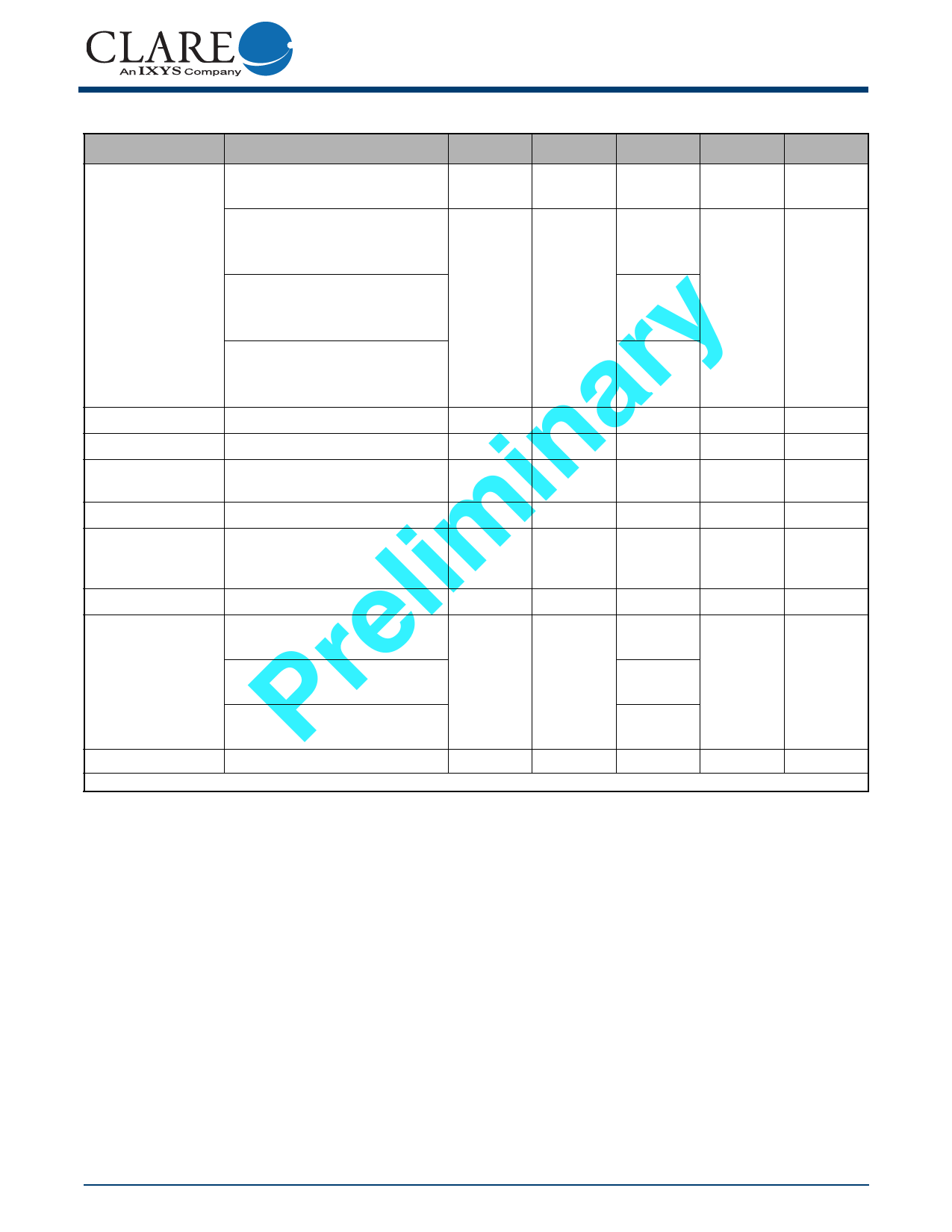
CPC7595
1.6.3 Ringing Switch, SW4
Parameter
Test Conditions
Symbol Minimum Typical Maximum
Unit
VSW4 (differential) = RLINE to RRINGING
All-Off state.
+25° C
VSW (differential) = -255 V to +210 V
0.05
VSW (differential) = +255 V to -210 V
Off-State
Leakage Current
On Resistance
On Voltage
On-State
Leakage Current
+85° C
VSW (differential) = -270 V to +210 V
VSW (differential) = +270 V to -210 V
-40° C
VSW (differential) = -245 V to +210 V
VSW (differential) = +245 V to -210 V
ISW (on) = ±70 mA, ±80 mA
ISW (on) = ± 1 mA
Inputs set for ringing -Measure ringing
generator current to ground.
ISW
RON
VON
IRINGING
-
0.1
1
y0.05
r -
10
15
a-
1.5
3
in-
0.1
0.25
μA
Ω
V
mA
Steady-State Current*
Surge Current*
Release Current
Logic input to switch
output isolation
Inputs set for ringing mode.
Ringing switches on, all other switches
off. Apply ±1 kV 10x1000 μs pulse with
lim appropriate protection in place.
SW4 transition from on to off.
+25° C, Logic inputs = gnd,
VSW (RRINGING, RLINE) = ±320 V
e +85° C, Logic inputs = gnd,
r VSW (RRINGING, RLINE) = ±330 V
-40° C, Logic inputs = gnd,
P VSW (RRINGING, RLINE) = ±310 V
ISW
ISW
IRINGING
ISW
-
-
-
-
-
150
mA
-
2
A
450
-
μA
0.1
0.3
1
μA
0.1
dv/dt sensitivity
-
-
-
500
-
V/μs
*Secondary protection and current limiting must prevent exceeding this parameter.
R00B
www.clare.com
7
Share Link: 