DM9081 데이터 시트보기 (PDF) - Unspecified
부품명
상세내역
제조사
DM9081 Datasheet PDF : 22 Pages
| |||
DM9081
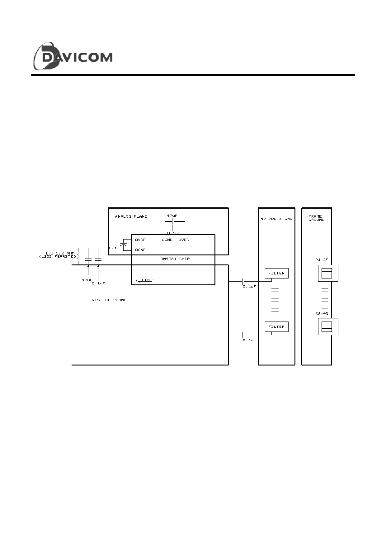
Power Plane
The board power planes must be separated into analog and
digital portions. The +5V and ground planes can be laid
out according to the configuration shown in Figure 8. The
analog portion should be located under the analog power
pins of the DM9081 chip and the AUI logic. The digital
portion should be located close enough to the 10BASE-T
filter to attach a 0.1mF capacitor to the filter ground pin.
Extending the digital power plane under the 10BASE-T
filter is not recommended. The analog and digital power
planes should be connected at a single point with either a
1.8-2.2Ω or 120Z ferrite bead. In the diagram below, a
47mF capacitor is used in parallel with a 0.1mF capacitor
to connect the analog and digital planes. Shielded RJ-45
connectors are recommended. The shielded pins should be
tied to the frame ground. Depending on the characteristics
of the 10BASE-T filter, either the frame ground or a void
in the planes should be extended under the filters. Consult
the filter manufacturer to determine if the frame ground is
needed to minimize the effects of cross-talk within the
filters.
Figure 8. DM9081 Device Power Plane Recommendations
20
Final
Version: DM9081-DS-F01
April 22, 1997
Share Link: 