4543ILZ(2007) 데이터 시트보기 (PDF) - Intersil
부품명
상세내역
제조사
4543ILZ Datasheet PDF : 17 Pages
| |||
Typical Performance Curves (Continued)
EL4543
JEDEC JESD51-7 HIGH EFFECTIVE THERMAL
CONDUCTIVITY TEST BOARD - QFN EXPOSED
DIEPAD SOLDERED TO PCB PER JESD51-5
3
2.500W
2.5
2
1.5
θJA(4=m40m°QCx/FW4Nm2m0 )
1
0.5
0
0
25
50
75 85 100 125 150
AMBIENT TEMPERATURE (°C)
FIGURE 37. PACKAGE POWER DISSIPATION vs AMBIENT TEMPERATURE
Operational Description and Application
Information
Introduction
The EL4543 is designed to differentially drive composite
RGB video signals onto twisted pair lines, while
simultaneously encoding horizontal and vertical sync signals
as common mode output. The entire video signal plus sync
can therefore be transmitted on 3 twisted pairs of wire. When
utilizing CAT-5 cable, the 4th available twisted pair can be
used for transmission of audio, data or control information.
The distribution of composite video over standard CAT-5
cable enables enormous cost and labor savings compared
with traditional coaxial cable, when considering both the
relative low price and ease of pulling CAT-5 cable.
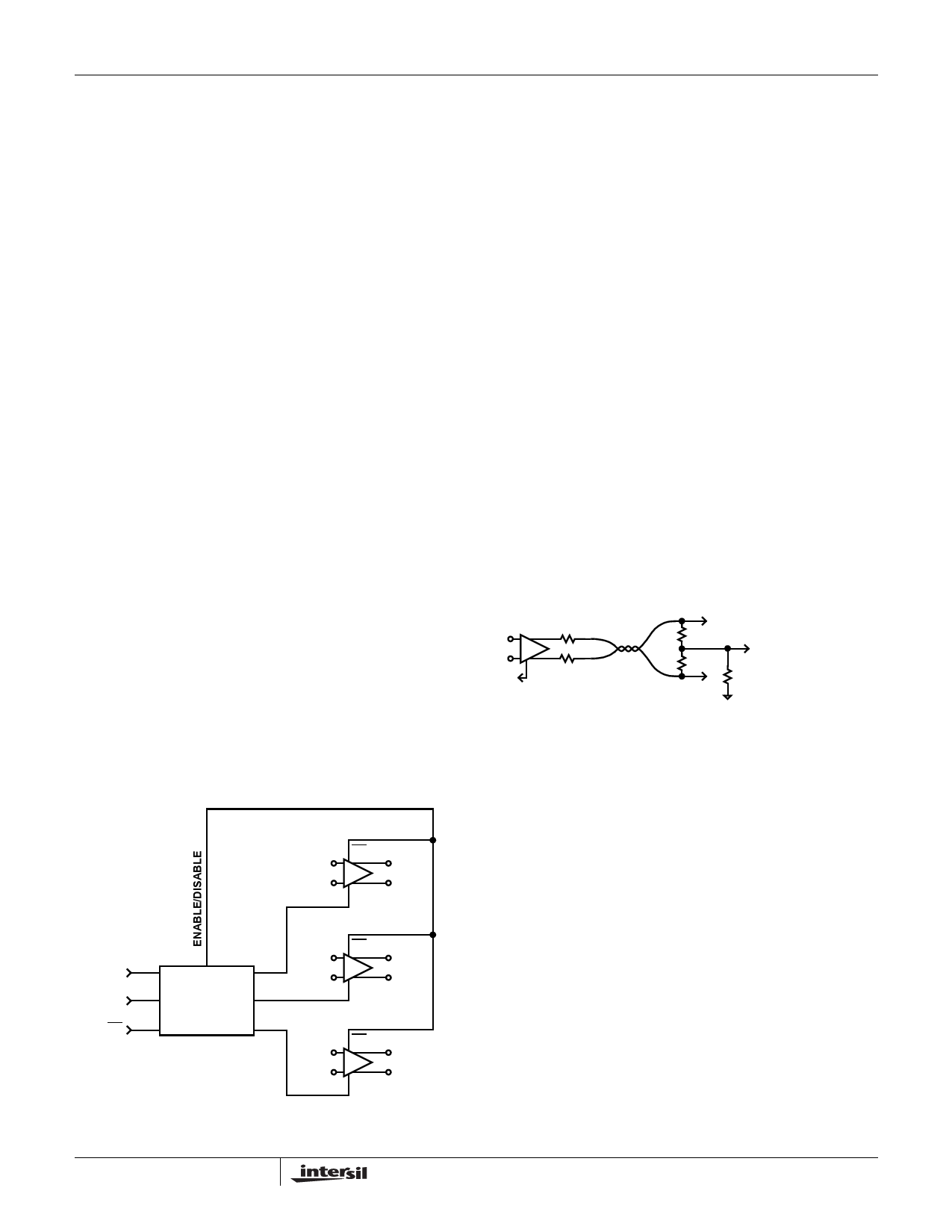
Functional Description
The EL4543 provides three fully differential high-speed
amplifiers, suitable for driving high-resolution composite
video signals onto twisted pair or standard coaxial cable.
The input common-mode range extends to the negative rail,
allowing simple ground-referenced input termination to be
used with a single supply. The amplifiers provide a fixed gain
of +2 to compensate for standard video cable termination
schemes. Horizontal and Vertical sync signals (HSYNC and
VSYNC) are passed to an internal Logic Encoding Block to
encode the sync information as three discrete signals of
different voltage levels. Generally, in differential amplifiers an
external VREF pin is used to control the common mode level
of the differential output; in the case of the EL4543 the VREF
of each of the three internal amplifier channels receives a
signal from the Logic Encoding Block with encoded HSYNC
and VSYNC information. The final output consists of three
fully differential video signals, with sync encoded on the
common mode of each of the three RGB differential signals.
HSYNC and VSYNC can easily be separated from the
differential output signals, decoded and transmitted along
with the RGB video signals to the video monitor.
EN
+
INA
-
+
-
+
OUTA
-
VREF
VSYNC
HSYNC
EN
LOGIC
DECODING
RCM
GCM
BCM
EN
+
INB
-
+
-
+
OUTB
-
VREF
EN
+
INC
-
+
-
+
OUTC
-
VREF
FIGURE 38. BLOCK DIAGRAM EL4543
Sync Transmission
The EL4543 encodes HSYNC and VSYNC signals on the
common mode output of the differential video signals; Red,
Green and Blue respectively. Data Sheet Figures 16, 17 and
18 clearly illustrate that the sum of the common mode
voltages results in a fixed average DC level with no AC
content and illustrates the logic levels. This eliminates EMI
radiation into any common mode signal along the twisted
pairs of CAT 5 cable.
11
FN7325.9
January 5, 2007
Share Link: 