GS-R24F0001.0(2006) 데이터 시트보기 (PDF) - STMicroelectronics
부품명
상세내역
제조사
GS-R24F0001.0 Datasheet PDF : 12 Pages
| |||
GS-R24F
1
Pin settings
Pin settings
1.1
Pin connection
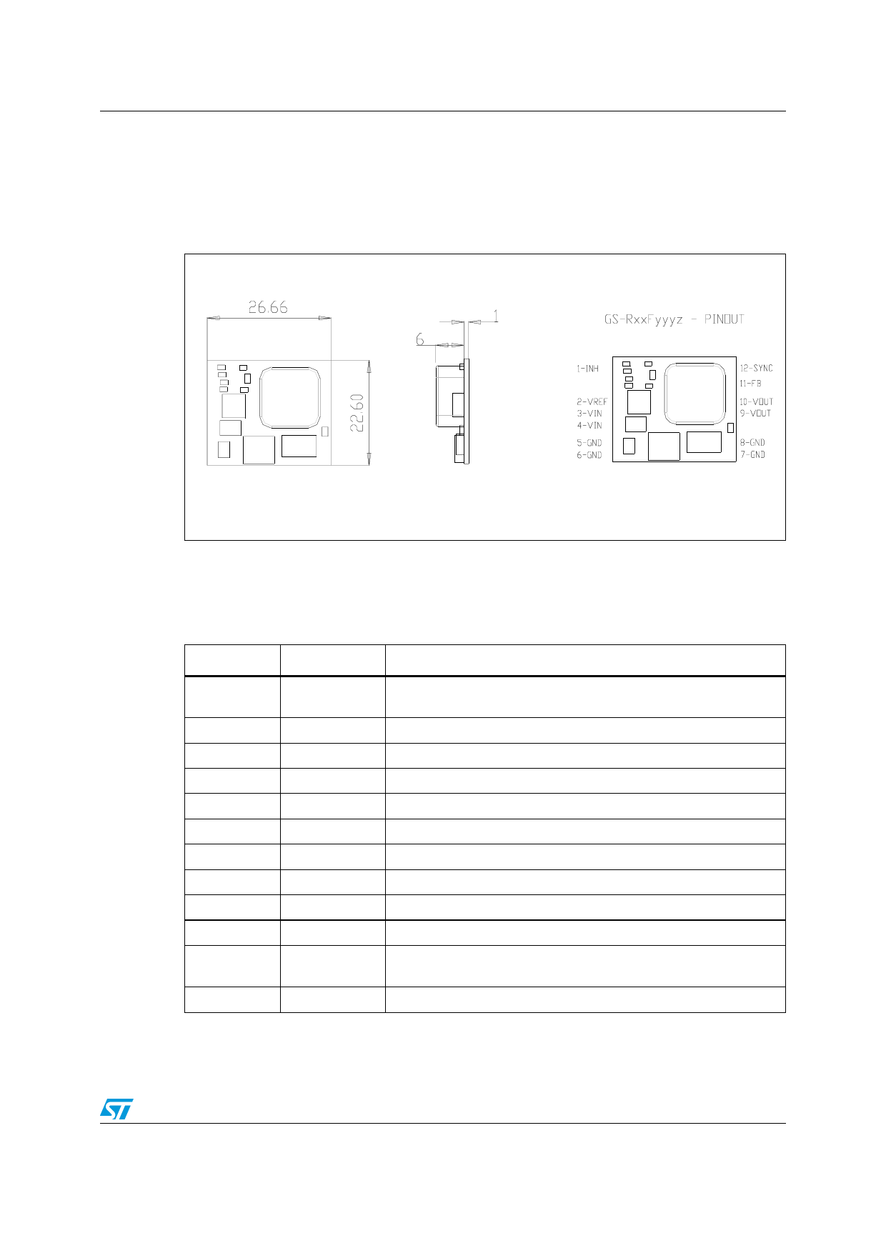
Figure 1. Pin connection and mechanical data (dimensions in mm)
1.2
Pin description
Table 1. Pin description
Name
Function
Description
1
INH
A logic high level disables the device. When the pin is open, an
internal pull up disables the device
2
Vref
3.3V reference voltage
3
Input +
DC input voltage
4
Input +
DC input voltage
5
Input GND Return for input voltage source
6
Input GND Return for input voltage source
7
Output GND Return for output voltage source
8
Output GND Return for output voltage source
9
Vout
Regulated power output
10
Vout
Regulated power output
11
FB
Feedback input, available on adjustable device and on request for
additional compensation
12
Sync
Master/Slave synchronization
3/12
Share Link: 