LT1961EMS8E 데이터 시트보기 (PDF) - Linear Technology
부품명
상세내역
제조사
LT1961EMS8E Datasheet PDF : 16 Pages
| |||
LT1961
APPLICATIONS INFORMATION
CATCH DIODE
The suggested catch diode (D1) is a UPS120 or 1N5818
Schottky. It is rated at 1A average forward current and
20V/30V reverse voltage. Typical forward voltage is 0.5V
at 1A. The diode conducts current only during switch off
time. Peak reverse voltage is equal to regulator output
voltage. Average forward current in normal operation is
equal to output current.
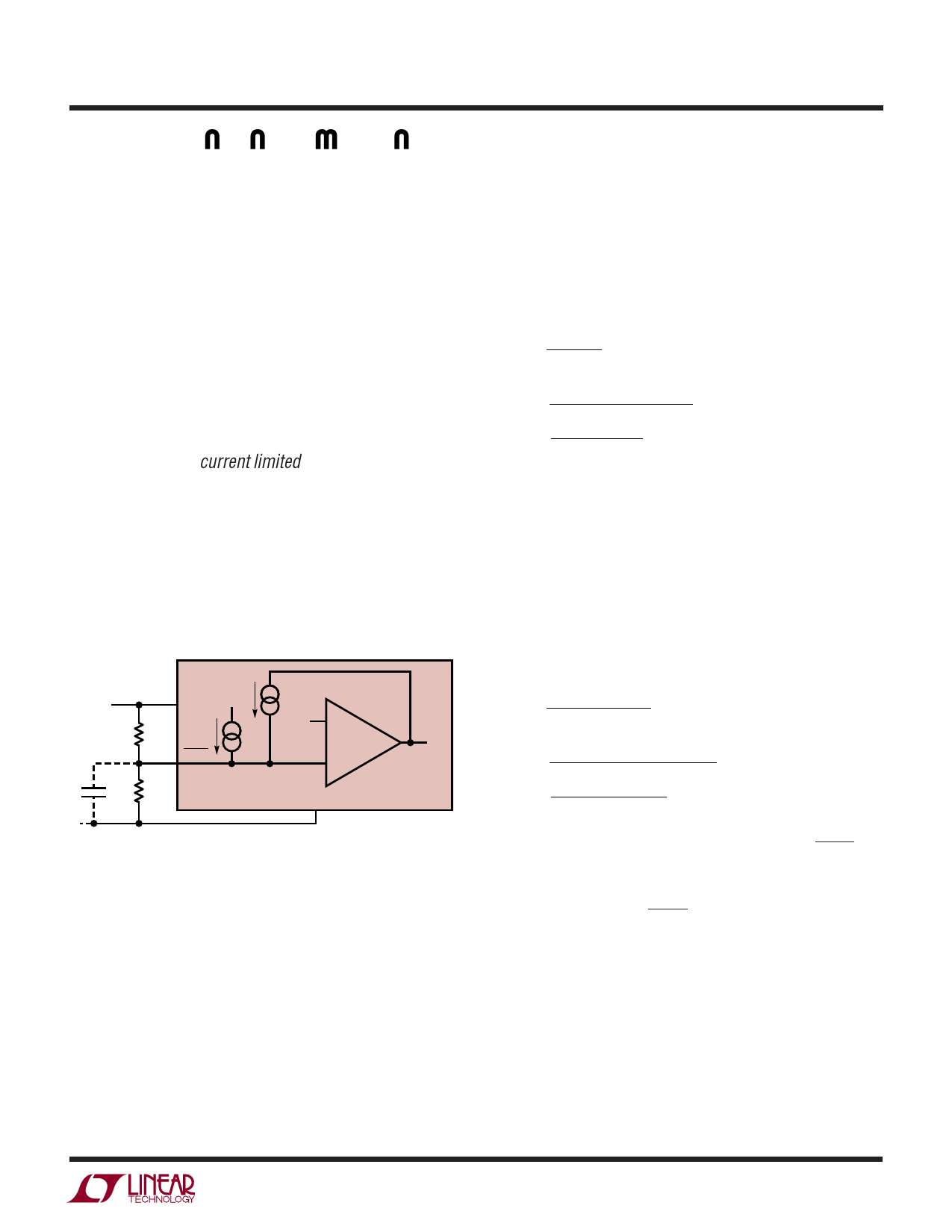
SHUTDOWN AND UNDERVOLTAGE LOCKOUT
Figure 4 shows how to add undervoltage lockout (UVLO)
to the LT1961. Typically, UVLO is used in situations where
the input supply is current limited, or has a relatively high
source resistance. A switching regulator draws constant
power from the source, so source current increases as
source voltage drops. This looks like a negative resistance
load to the source and can cause the source to current limit
or latch low under low source voltage conditions. UVLO
prevents the regulator from operating at source voltages
where these problems might occur.
INPUT
LT1961
IN
R1
SHDN
7μA
1.35V
3μA
C1
R2
GND
VCC
1961 F04
Figure 4. Undervoltage Lockout
An internal comparator will force the part into shutdown
below the minimum VIN of 2.6V. This feature can be used
to prevent excessive discharge of battery-operated sys-
tems. If an adjustable UVLO threshold is required, the
shutdown pin can be used. The threshold voltage of the
shutdown pin comparator is 1.35V. A 3μA internal current
source defaults the open pin condition to be operating (see
Typical Performance Graphs). Current hysteresis is added
above the SHDN threshold. This can be used to set voltage
hysteresis of the UVLO using the following:
R1= VH − VL
7μA
( ) R2 =
1.35V
VH − 1.35V
+ 3μA
R1
VH – Turn-on threshold
VL – Turn-off threshold
Example: switching should not start until the input is
above 4.75V and is to stop if the input falls below 3.75V.
VH = 4.75V
VL = 3.75V
R1= 4.75V − 3.75V = 143k
7μA
( ) R2 =
1.35V
4.75V − 1.35V
= 50.4k
+ 3μA
143k
Keep the connections from the resistors to the SHDN pin
short and make sure that the interplane or surface capaci-
tance to the switching nodes are minimized. If high resis-
tor values are used, the SHDN pin should be bypassed with
a 1nF capacitor to prevent coupling problems from the
switch node.
1961fa
9
Share Link: 