LTC2282 데이터 시트보기 (PDF) - Linear Technology
부품명
상세내역
제조사
LTC2282 Datasheet PDF : 24 Pages
| |||
LTC2282
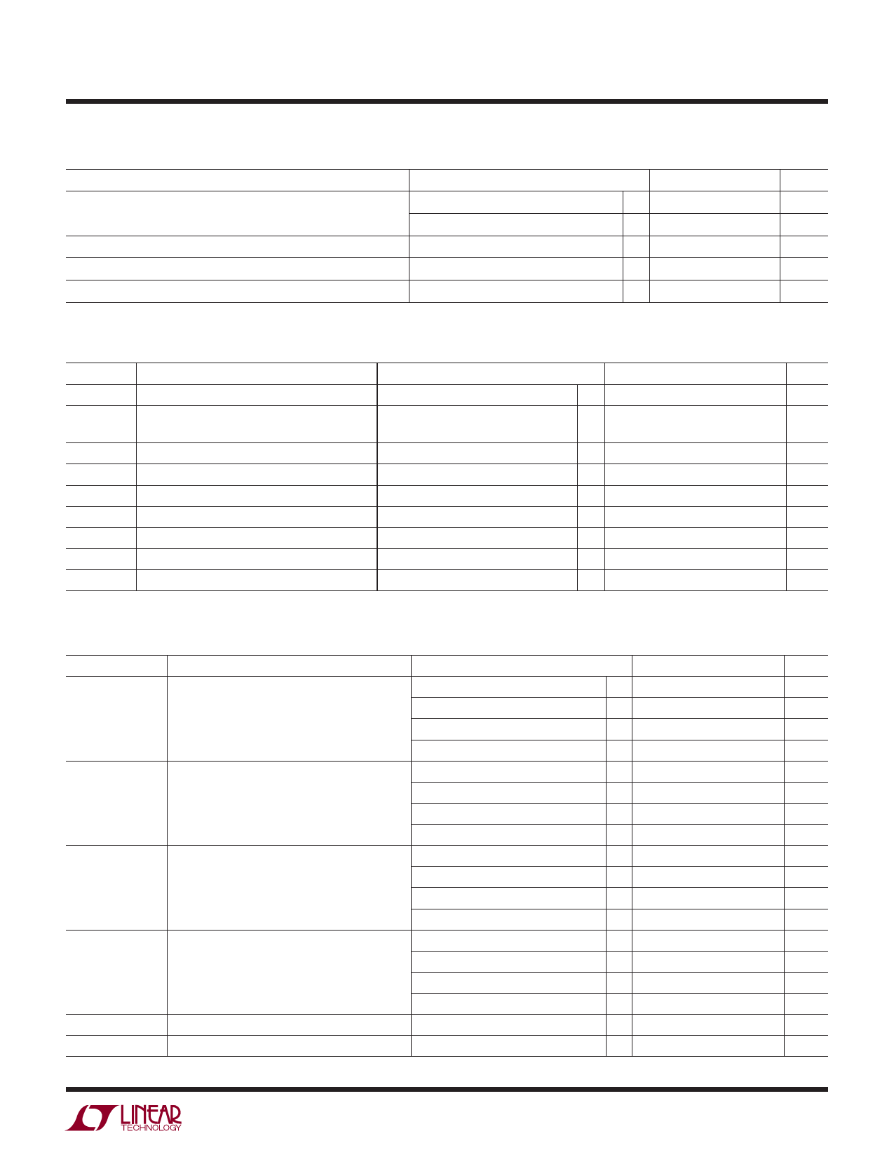
CONVERTER CHARACTERISTICS The l denotes the specifications which apply over the full operating
temperature range, otherwise specifications are at TA = 25°C. (Note 4)
PARAMETER
CONDITIONS
MIN TYP MAX UNITS
Full-Scale Drift
Internal Reference
±30
ppm/°C
External Reference
±5
ppm/°C
Gain Matching
External Reference
±0.3
%FS
Offset Matching
±2
mV
Transition Noise
SENSE = 1V
0.3
LSBRMS
ANALOG INPUT The l denotes the specifications which apply over the full operating temperature range, otherwise
specifications are at TA = 25°C. (Note 4)
SYMBOL
VIN
VIN,CM
IIN
ISENSE
IMODE
tAP
tJITTER
CMRR
PARAMETER
Analog Input Range (AIN+ – AIN–)
Analog Input Common Mode (AIN+ + AIN–)/2
Analog Input Leakage Current
SENSEA, SENSEB Input Leakage
CONDITIONS
2.85V < VDD < 3.4V (Note 7)
Differential Input Drive (Note 7)
Single Ended Input Drive (Note 7)
0V < AIN+, AIN– < VDD
0V < SENSEA, SENSEB < 1V
MODE Input Leakage Current
Sample-and-Hold Acquisition Delay Time
0V < MODE < VDD
Sample-and-Hold Acquisition Delay Time Jitter
Analog Input Common Mode Rejection Ratio
MIN
TYP
MAX UNITS
l
±0.5V to ±1V
V
l
1
1.5
1.9
V
l 0.5
1.5
2
V
l –1
1
μA
l –3
3
μA
l –3
3
μA
0
ns
0.2
psRMS
80
dB
Full Power Bandwidth
Figure 8 Test Circuit
575
MHz
DYNAMIC ACCURACY The l denotes the specifications which apply over the full operating temperature range,
otherwise specifications are at TA = 25°C. AIN = –1dBFS. (Note 4)
SYMBOL
PARAMETER
CONDITIONS
MIN TYP MAX UNITS
SNR
Signal-to-Noise Ratio
5MHz Input
30MHz Input
70MHz Input
140MHz Input
70.1
dB
70.1
dB
l 68.5 70
dB
69.7
dB
SFDR
Spurious Free Dynamic Range
2nd or 3rd Harmonic
5MHz Input
30MHz Input
88
dB
86
dB
SFDR
Spurious Free Dynamic Range
4th Harmonic or Higher
70MHz Input
140MHz Input
5MHz Input
30MHz Input
l 72
84
dB
79
dB
90
dB
90
dB
70MHz Input
l 79
90
dB
140MHz Input
90
dB
S/(N+D)
Signal-to-Noise Plus Distortion Ratio
5MHz Input
30MHz Input
70MHz Input
70
dB
70
dB
l 67.5 69.9
dB
140MHz Input
68.7
dB
IMD
Intermodulation Distortion
Crosstalk
fIN = 40MHz, 41MHz
fIN = 100MHz
85
dB
–110
dB
2282fb
3
Share Link: 