LTC4096EDD 데이터 시트보기 (PDF) - Linear Technology
부품명
상세내역
제조사
LTC4096EDD Datasheet PDF : 16 Pages
| |||
LTC4096/LTC4096X
APPLICATIONS INFORMATION
Using a Single Charge Current Program Resistor
In applications where the programmed wall adapter charge
current and USB charge current are the same, a single
program resistor can be used to set both charge currents.
Figure 3 shows a charger circuit that uses one charge cur-
rent program resistor. In this circuit, one resistor programs
the same charge current for each input supply.
ICHRG(DC)
=
ICHRG(USB)
=
1000V
RISET
The LTC4096 can also program the wall adapter charge
current and USB charge current independently using two
program resistors, RIDC and RIUSB. Figure 4 shows a
charger circuit that sets the wall adapter charge current
to 800mA and the USB charge current to 500mA.
DCIN
1
Stability Considerations
The constant-voltage mode feedback loop is stable without
any compensation provided a battery is connected to the
charger output. However, a 4.7µF capacitor with a 1Ω
series resistor is recommended at the BAT pin to keep
the ripple voltage low when the battery is disconnected.
When the charger is in constant-current mode, the charge
current program pin (IDC or IUSB) is in the feedback loop,
not the battery. The constant-current mode stability is
affected by the impedance at the charge current program
pin. With no additional capacitance on this pin, the charger
is stable with program resistor values as high as 20KΩ
(ICHRG = 50mA); however, additional capacitance on these
nodes reduces the maximum allowed program resistor.
USBIN
2
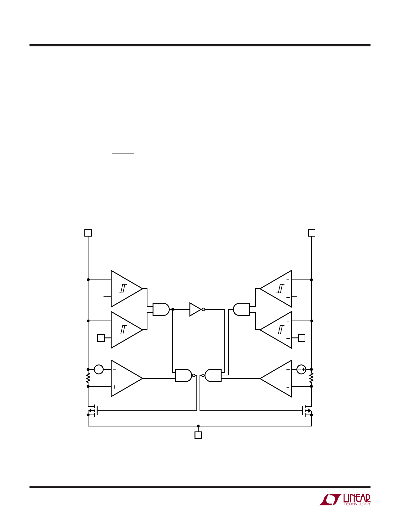
+
4.2V –
DCIN UVLO
+
BAT
10 –
∆V
+–
–
CURR-LIM
+
DCON
DCON USBON
4V
USBIN UVLO
BAT
10
∆V
CURR-LIM
12
3 120mA MAX
PWR
4096 BD
Figure 2. Input Power Present Output (PWR) Circuit
4096xf
Share Link: 