MAX9170EUE 데이터 시트보기 (PDF) - Maxim Integrated
부품명
상세내역
제조사
MAX9170EUE Datasheet PDF : 19 Pages
| |||
4-Port LVDS and LVTTL-to-LVDS Repeaters
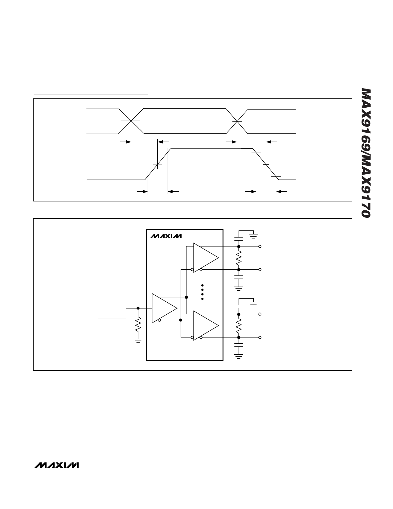
Test Circuits and Timing Diagrams (continued)
IN-
VCM = 1.2V
IN+
tPLH
80%
0V
VOD = (VOUT_+) - (VOUT_-)
20%
VOD
tR
Figure 12. MAX9169 Propagation Delay and Transition Time Waveforms, tSK(p)
VCM = 1.2V
tPHL
80%
1.4V
1.0V
0V
20%
tF
MAX9170
PULSE
IN
GENERATOR
50Ω
CL
10pF
OUT1+
RL
100Ω
OUT1-
CL
10pF
CL
10pF
OUT4+
RL
100Ω
OUT4-
CL
10pF
Figure 13. MAX9170 Propagation Delay and Transition Time Test Circuit
______________________________________________________________________________________ 13
Share Link: 