PCA9545CPW118 데이터 시트보기 (PDF) - NXP Semiconductors.
부품명
상세내역
제조사
PCA9545CPW118 Datasheet PDF : 32 Pages
| |||
NXP Semiconductors
PCA9545A/45B/45C
4-channel I2C-bus switch with interrupt logic and reset
7. Characteristics of the I2C-bus
The I2C-bus is for 2-way, 2-line communication between different ICs or modules. The two
lines are a serial data line (SDA) and a serial clock line (SCL). Both lines must be
connected to a positive supply via a pull-up resistor when connected to the output stages
of a device. Data transfer may be initiated only when the bus is not busy.
7.1 Bit transfer
One data bit is transferred during each clock pulse. The data on the SDA line must remain
stable during the HIGH period of the clock pulse, as changes in the data line at this time
are interpreted as control signals (see Figure 10).
6'$
6&/
Fig 10. Bit transfer
GDWDOLQH
VWDEOH
GDWDYDOLG
FKDQJH
RIGDWD
DOORZHG
PED
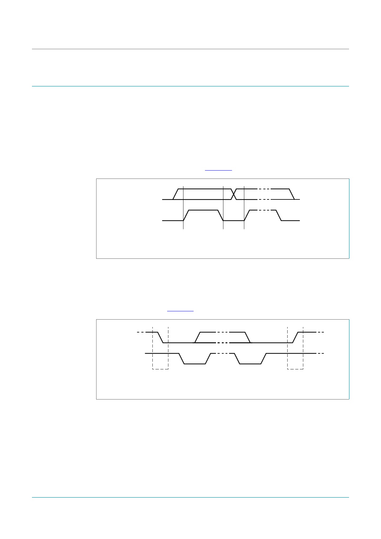
7.2 START and STOP conditions
Both data and clock lines remain HIGH when the bus is not busy. A HIGH-to-LOW
transition of the data line, while the clock is HIGH is defined as the START condition (S).
A LOW-to-HIGH transition of the data line while the clock is HIGH is defined as the
STOP condition (P) (see Figure 11).
6'$
6&/
6
67$57FRQGLWLRQ
Fig 11. Definition of START and STOP conditions
3
6723FRQGLWLRQ
PED
PCA9545A_45B_45C
Product data sheet
All information provided in this document is subject to legal disclaimers.
Rev. 9 — 5 May 2014
© NXP Semiconductors N.V. 2014. All rights reserved.
10 of 32
Share Link: 