STV0196 데이터 시트보기 (PDF) - STMicroelectronics
부품명
상세내역
제조사
STV0196 Datasheet PDF : 23 Pages
| |||
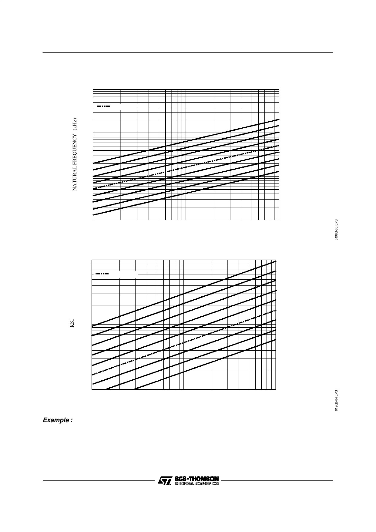
FUNCTIONAL DESCRIPTION (continued)
Figure 1 : Natural Frequency for Fs = 20MBauds
100
res e t value
10
1
STV0196B
be ta_tmg
9
8
7
6
5
4
3
2
1
0.1
0 .0 001
Figure 2 : Damping Factor
10
0.001
VCO Re lative Fre quency Ra nge (∆f)
re se t value
1
0.01
8
7
6
5
4
3
2
1
0
2a lpha _tmg
- beta _tmg
0.1
0.0001
0 .0 01
0.01
VCO Relative Frequency Ra nge (∆f)
Example :
the VCO is trimmed from 39.9MHz to 40.1MHz when the VCO control output CLKREC goes from duty
cycle 0 to 100%. The peak-to-peak relative range is therefore 0.5% and ∆f = 0.0025 ; the reset values of
the parameters (alpha_tmg = 4, beta_tmg = 5) leads to a natural frequency of 2.6kHz, with a damping
factor of 0.84.
9/23
Share Link: 