WM8972LEFL/R 데이터 시트보기 (PDF) - Wolfson Microelectronics plc
부품명
상세내역
제조사
WM8972LEFL/R Datasheet PDF : 49 Pages
| |||
Preliminary Technical Data
WM8972L
AUDIO INTERFACE CONTROL
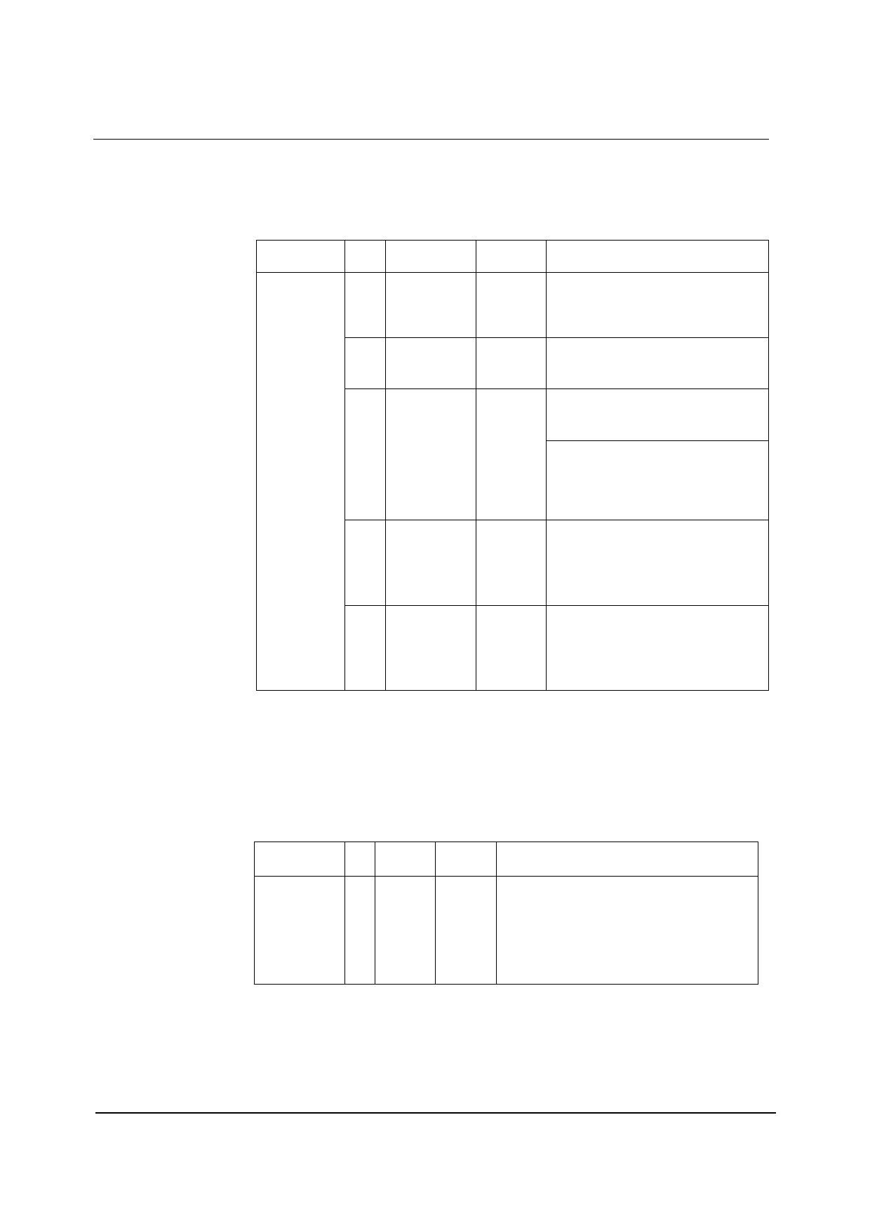
The register bits controlling audio format, word length and master / slave mode are summarised in
Table 24. MS selects audio interface operation in master or slave mode. In Master mode BCLK,
ADCLRC and DACLRC are outputs. The frequency of ADCLRC and DACLRC is set by the sample
rate control bits SR[4:0] and USB. In Slave mode BCLK, ADCLRC and DACLRC are inputs.
REGISTER
ADDRESS
R7 (07h)
Digital Audio
Interface
Format
BIT
LABEL
7
BCLKINV
6
MS
4
LRP
3:2 WL[1:0]
1:0 FORMAT[1:0]
Table 24 Audio Data Format Control
DEFAULT
DESCRIPTION
0
BCLK invert bit (for master & slave
modes)
0 = BCLK not inverted
1 = BCLK inverted
0
Master / Slave Mode Control
1 = Enable Master Mode
0 = Enable Slave Mode
0
right, left & i2s modes – LRCLK polarity
1 = invert LRCLK polarity
0 = normal LRCLK polarity
DSP Mode – mode A/B select
1 = MSB is available on 1st BCLK rising
edge after LRC rising edge (mode B)
0 = MSB is available on 2nd BCLK rising
edge after LRC rising edge (mode A)
10
Audio Data Word Length
11 = 32 bits (see Note)
10 = 24 bits
01 = 20 bits
00 = 16 bits
10
Audio Data Format Select
11 = DSP Mode
10 = I2S Format
01 = Left justified
00 = Right justified
Note: Right Justified mode does not support 32-bit data.
AUDIO INTERFACE OUTPUT TRISTATE
Register bit TRI, register 24(18h) bit[3] can be used to tristate the ADCDAT pin and switch ADCLRC,
DACLRC and BCLK to inputs. In Slave mode (MASTER=0) ADCLRC, DACLRC and BCLK are by
default configured as inputs and only ADCDAT will be tri-stated, (see Table 25).
REGISTER BIT LABEL DEFAULT
ADDRESS
DESCRIPTION
R24(18h)
Additional
Control (2)
3
TRI
0
Tristates ADCDAT and switches ADCLRC,
DACLRC and BCLK to inputs.
0 = ADCDAT is an output, ADCLRC, DACLRC
and BCLK are inputs (slave mode) or outputs
(master mode)
1 = ADCDATE is tristated, ADCLRC, DACLRC
and BCLK are inputs
Table 25 Tri-stating the Audio Interface
w
PTD Rev 2.2 June 2004
31
Share Link: 