2SB1132 데이터 시트보기 (PDF) - Willas Electronic Corp.
부품명
상세내역
제조사
2SB1132 Datasheet PDF : 3 Pages
| |||
WILLAS
SO1.0TA-S8U9RFPAClaE sMOtiUcN-TESnCHcOaTpTKsYuBlAaRtReIETRrRaEnCTsIFiIsERtoS r-2s0V- 200V
SOD-123+ PACKAGE
FM120-M+
2SB1132THRU
FM1200-M+
Pb Free Product
Features
• Batch process design, excellent power dissipation offers
better reverse leakage current and thermal resistance.
• Low profile surface mounted application in order to
Outline Drawing optimize board space.
• Low power loss, high efficiency.
• High current capability, low forward voltage drop.
• High surge capability.
• Guardring for overvoltage protection.
• Ultra high-speed switching.
• Silicon epitaxial planar chip, metal silicon junction.
• Lead-free parts meet environmental standards of
MIL-STD-19500 /228
• RoHS product for packing code suffix "G"
Halogen free product for packing code suffix "H"
Mechanical data
.181(4.60)
• Epoxy : UL94-V0 rated flame retardant
.173(4.39)
• Case : Molded plastic, SOD-123H
,
• Terminals :Plated terminals, solderable per MIL-STD-750
Method 2026
•
Polarity
:
Indicated
by
cathode
.061REF
band
• Mounting Position : Any
(1.55)REF
• Weight : Approximated 0.011 gram
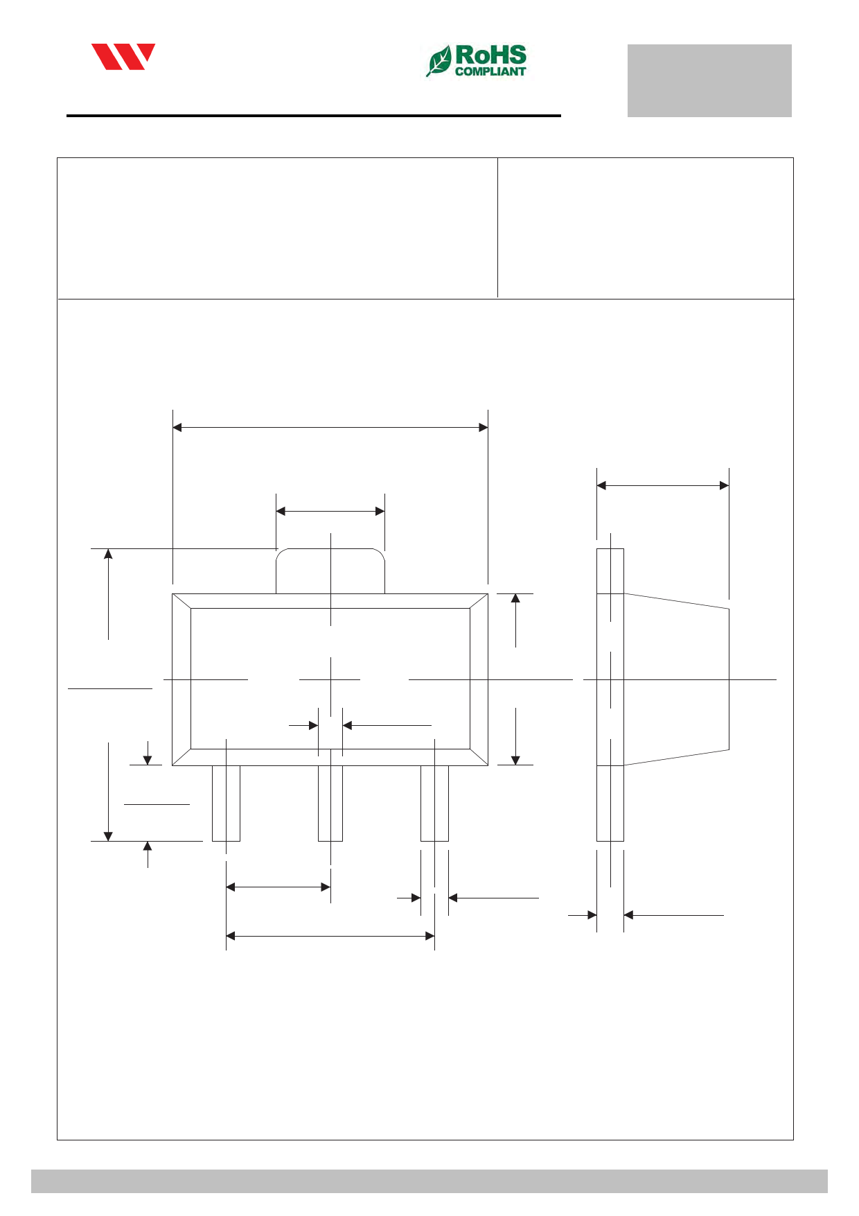
Package outline
SOD-123H
S O T- 8 9 0.146(3.7)
0.130(3.3)
0.012(0.3) Typ.
0.071(1.8)
0.056(1.4)
0.040(1.0)
0.024(0.6)
0.031(0.8) Typ.
.063(1.60)
0.031(0.8) Typ.
.055(1.40)
Dimensions in inches and (millimeters)
MAXIMUM RATINGS AND ELECTRICAL CHARACTERISTICS
Ratings at 25℃ ambient temperature unless otherwise specified.
Single phase half wave, 60Hz, resistive of inductive load.
For capacitive load, derate current by 20%
RATINGS
.M1a6r7kin(g4C.2od5e)
Maximum Recurrent Peak Reverse Voltage
.154(3.91)
Maximum RMS Voltage
Maximum DC Blocking Voltage
Maximum Average Forward Rectified Current
SYMBOL FM120-MH FM130-MH FM140-MH FM150-MH FM160-MH FM180-MH FM1100-MH FM1150-MH FM1200-MH U
12
13 .1104 2(2.6105 ) 16
18
10
115 120
VRRM
20
30 .04091(2.350) 60
80
100
150
200 V
V.R0M2S 3(0.1548) 21
28
35
42
V.D0C16(0.2400) 30
40
50
60
56
70
105
140 V
80
100
150
200 V
IO
1.0
A
Peak Forward Surge Current 8.3 ms single half sine-wave IFSM
superimpos.e0d4o7n (ra1te.d2l)oad (JEDEC method)
30
A
Typical Th.e0rm3a1l (R0es.i8st)ance (Note 2)
RΘJA
40
℃
Typical Junction Capacitance (Note 1)
CJ
120
Operating Temperature Range
TJ
-55 to +125
-55 to +150
Storage Temperature Range
TSTG
- 65 to +175
.060TYP
.197(0.52)
CHARACTERI(S1T.I5CS0)TYP
SYMBOL FM120-MH FM13.00-M1H3F(M014.30-M2H) FM150-MH FM160-MH F.M018107-M(H0F.M41410)0-MH FM1150-MH FM1200-MH U
Maximum Forward Voltage at 1.0A DC
VF
.118TYP
0.50
0.70
.014(00.8.535)
0.9
0.92 V
Maximum Average Reverse Current at
Rated DC Blocking Voltage
@T
@T
A=25℃
A(=312.50℃)T
YPIR
0.5
m
10
NOTES:
1- Measured at 1 MHZ and applied reverse voltage of 4.0 VDC.
2- Thermal Resistance From Junction to Ambient
2012-06
2012-0
Dimensions in inches and (millimeters)
WILLAS ELECTRONIC CORP
Rev.C
WILLAS ELECTRONIC CORP.
Share Link: 