MAX8601ETD(2005) 데이터 시트보기 (PDF) - Maxim Integrated
부품명
상세내역
제조사
MAX8601ETD
(Rev.:2005)
(Rev.:2005)
Maxim Integrated
MAX8601ETD Datasheet PDF : 12 Pages
| |||
Single-/Dual-Input 1-Cell Li+ Chargers with
OVP Protection and Programmable Charge Timer
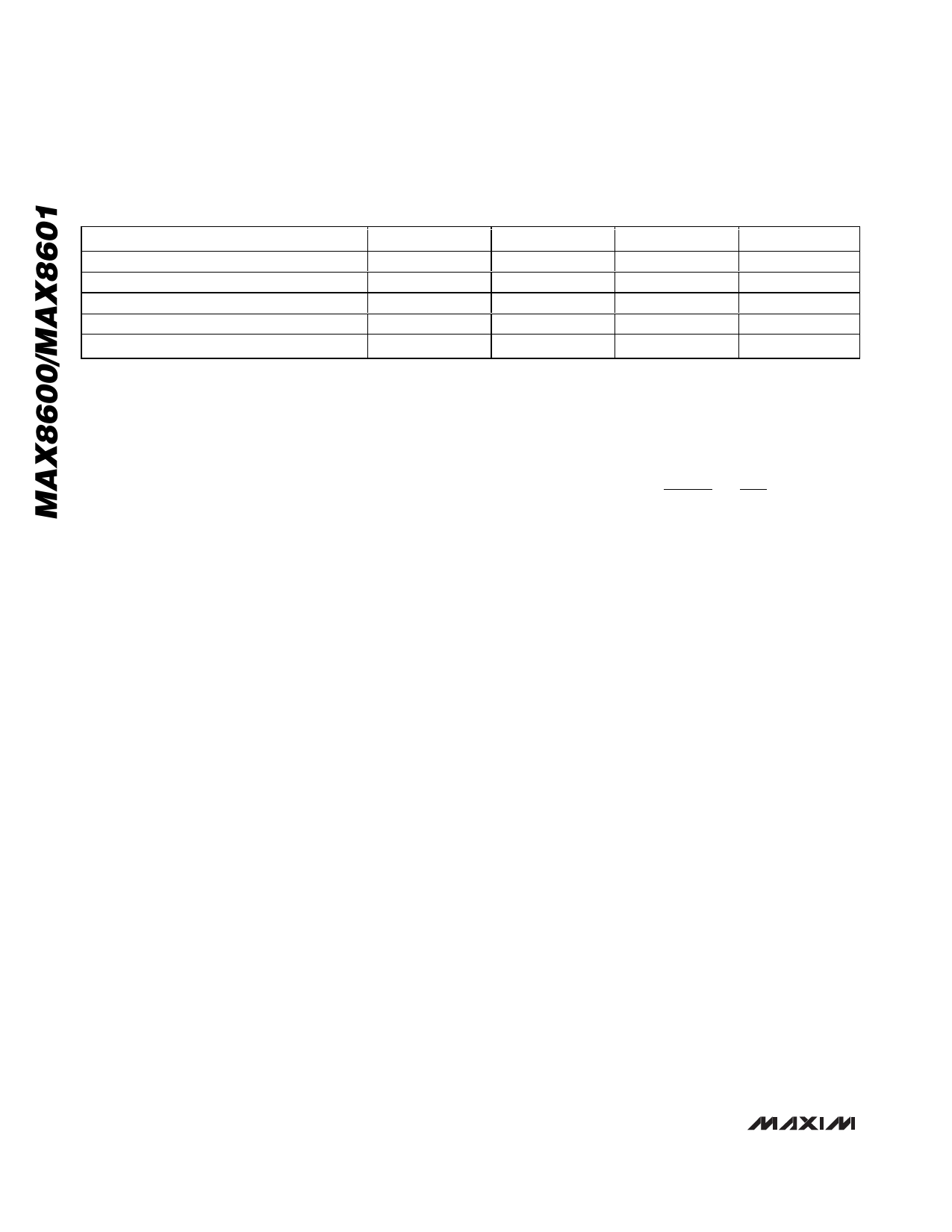
Table 1. Fault Temperatures for Different Thermistors
THERMISTOR BETA
Resistance at +25°C
Resistance at +50°C
Resistance at 0°C
Nominal Hot Trip Temperature
Nominal Cold Trip Temperature
3000
10,000Ω
4587.78Ω
25,140.55Ω
+55.14°C
-3.24°C
3250
10,000Ω
4299.35Ω
27,148.09Ω
+52.60°C
-1.26°C
3500
10,000Ω
4029.06Ω
29,315.94Ω
+50.46°C
+0.46°C
3750
10,000Ω
3775.75Ω
31,656.90Ω
+48.63°C
+1.97°C
Charge Current Selection
The maximum charging current from a supply connect-
ed to DC is programmed by an external resistor (RSETI)
connected from SETI to GND. Calculate the RSETI value
as follows:
RSETI = 1500 / ICHARGE(MAX)
where ICHARGE(MAX) is in amps and RSETI is in ohms.
SETI can also be used to monitor the actual charge-
current level. The output voltage at SETI is proportional
to the charging current as follows:
VSETI = (ICHARGE x RSETI) / 1000
Note that the prequal current for both USB and DC
input operation is 1/10 of the fast-charge current set by
RSETI. Also, the top-off charge-current threshold for
both USB and DC input operation is set to 7.5% of the
fast-charge current set by RSETI.
IPREQUAL = 150 / RSETI
ITOP-OFF = 112.5 / RSETI
Timer Capacitor Selection
The MAX8600/MAX8601 contain timers for prequal,
fast-charge, and top-off operation. These time periods
are determined by the capacitance from CT to GND. To
set the charge times, calculate CCT as follows:
TFASTCHARGE = 334min x (CCT / 0.068µF)
TPREQUAL = TTOPOFF = 34.8min x (CCT / 0.068µF)
Note that when charging at 100mA from the USB input
(MAX8601), the fast-charge timer is inhibited. When THM
halts charging, the timers stop and hold their value.
Battery Temperature Control
The MAX8600/MAX8601 monitor battery temperature
through a negative TC thermistor which is in close ther-
mal contact with the battery. Select a thermistor resis-
tance that is 10kΩ at +25°C and has a beta of 3500.
The IC compares the resistance from THM to GND and
suspends charging when it is greater than 28.3kΩ or
less than 3.94kΩ, which translates to a temperature of
0°C to +50°C. Table 1 shows the nominal temperature
limits that result from a wide range of available thermis-
tor temperature curves. The curves are defined by the
following equation:
RT
= R25°C ×
e⎧⎨⎪⎩⎪β⎡⎣⎢⎛⎝⎜
1⎞
T + 273⎠⎟
−
⎛
⎝⎜
1
298
⎞
⎠⎟
⎤⎫⎪
⎦⎥⎬⎭⎪
where β is the BETA term in Table 1.
Connect THM to GND to disable the temperature-con-
trol function. When RTHM disables charging, all timers
pause and hold their value.
Capacitor Selection
Connect a 2.2µF ceramic capacitor from BAT to GND
for proper stability. Connect a 1µF ceramic capacitor
from DC to GND. If using the USB input for the
MAX8601, bypass USB to GND with a 1µF ceramic
capacitor. Use a larger input bypass capacitor for high
charging currents to reduce supply noise. All capaci-
tors should be X5R dielectric or better. Be aware that
some capacitors have large voltage coefficients and
should be avoided.
Thermal Considerations
The MAX8600/MAX8601 are in a thermally enhanced
TDFN package with an exposed paddle. Connect the
exposed paddle of the package to a large copper
ground plane to provide a thermal contact between the
device and the circuit board. The exposed paddle
transfers heat away from the device, allowing the IC to
charge the battery with maximum current, while mini-
mizing the increase in die temperature. Note that the
MAX8600/MAX8601s’ thermal-limit control allows the
charger to be tolerant of thermally restricted PC board
layouts that are sometimes unavoidable in compact
portable designs. With such non-optimal layouts, the
charger still operates, but may reduce charge current
to manage temperature rise.
8 _______________________________________________________________________________________
Share Link: 