SC16IS740 데이터 시트보기 (PDF) - NXP Semiconductors.
부품명
상세내역
제조사
SC16IS740
NXP Semiconductors.
SC16IS740 Datasheet PDF : 63 Pages
| |||
NXP Semiconductors
SC16IS740/750/760
Single UART with I2C-bus/SPI interface, 64-byte FIFOs, IrDA SIR
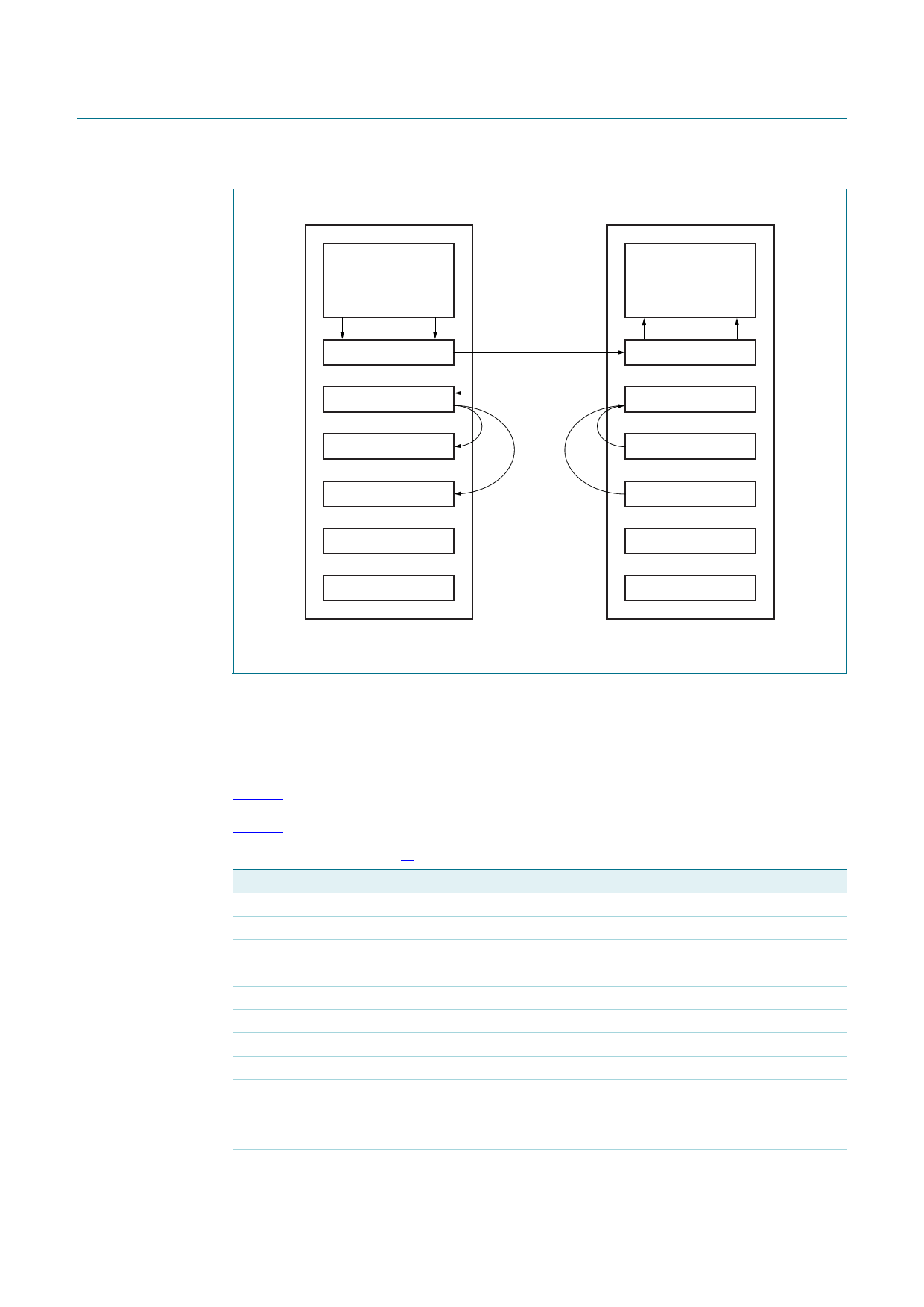
UART1
TRANSMIT FIFO
UART2
RECEIVE FIFO
PARALLEL-TO-SERIAL
SERIAL-TO-PARALLEL
data
Xoff–Xon–Xoff
SERIAL-TO-PARALLEL
PARALLEL-TO-SERIAL
Xon1 WORD
Xon1 WORD
Xon2 WORD
Xon2 WORD
Xoff1 WORD
Xoff1 WORD
Xoff2 WORD
compare
programmed
Xon-Xoff
characters
Fig 11. Example of software flow control
Xoff2 WORD
002aaa229
7.4 Reset and power-on sequence
7.4.1 Hardware reset, Power-On Reset (POR) and software reset
These three reset methods are identical and will reset the internal registers as indicated in
Table 4.
Table 4 summarizes the state of register.
Table 4. Register reset[1]
Register
Interrupt Enable Register
Interrupt Identification Register
FIFO Control Register
Line Control Register
Modem Control Register
Line Status Register
Modem Status Register
Enhanced Feature Register
Receiver Holding Register
Transmitter Holding Register
Transmission Control Register
Trigger Level Register
Reset state
all bits cleared
bit 0 is set; all other bits cleared
all bits cleared
reset to 0001 1101 (0x1D)
all bits cleared
bit 5 and bit 6 set; all other bits cleared
bits 0:3 cleared; bits 4:7 input signals
all bits cleared
pointer logic cleared
pointer logic cleared
all bits cleared.
all bits cleared.
SC16IS740_750_760
Product data sheet
All information provided in this document is subject to legal disclaimers.
Rev. 7 — 9 June 2011
© NXP B.V. 2011. All rights reserved.
13 of 63
Share Link: 