LTC5527 데이터 시트보기 (PDF) - Linear Technology
부품명
상세내역
제조사
LTC5527 Datasheet PDF : 28 Pages
| |||
LTC2262-12
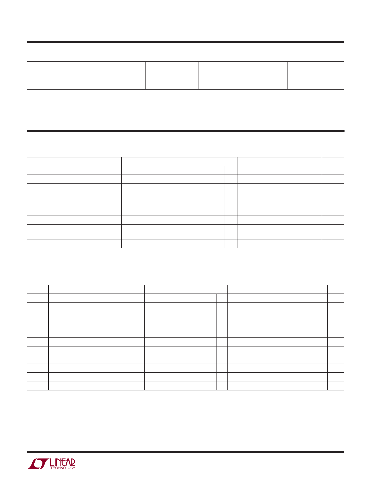
ORDER INFORMATION
LEAD FREE FINISH
TAPE AND REEL
PART MARKING*
PACKAGE DESCRIPTION
TEMPERATURE RANGE
LTC2262CUJ-12#PBF LTC2262CUJ-12#TRPBF LTC2262UJ-12
40-Lead (6mm × 6mm) Plastic QFN
0°C to 70°C
LTC2262IUJ-12#PBF
LTC2262IUJ-12#TRPBF
LTC2262UJ-12
40-Lead (6mm × 6mm) Plastic QFN
–40°C to 85°C
Consult LTC Marketing for parts specified with wider operating temperature ranges. *The temperature grade is identified by a label on the shipping container.
Consult LTC Marketing for information on non-standard lead based finish parts.
For more information on lead free part marking, go to: http://www.linear.com/leadfree/
For more information on tape and reel specifications, go to: http://www.linear.com/tapeandreel/
CONVERTER CHARACTERISTICS The l denotes the specifications which apply over the full operating
temperature range, otherwise specifications are at TA = 25°C. (Note 5)
PARAMETER
CONDITIONS
MIN
TYP
MAX
UNITS
Resolution (No Missing Codes)
l
12
Bits
Integral Linearity Error
Differential Analog Input (Note 6)
l
–1
±0.3
1
LSB
Differential Linearity Error
Differential Analog Input
l
–0.4
±0.1
0.4
LSB
Offset Error
(Note 7)
l
–9
±1.5
9
mV
Gain Error
Internal Reference
External Reference
±1.5
%FS
l
–1.5
±0.4
1.5
%FS
Offset Drift
±20
μV/°C
Full-Scale Drift
Internal Reference
External Reference
±30
ppm/°C
±10
ppm/°C
Transition Noise
External Reference
0.3
LSBRMS
ANALOG INPUT The l denotes the specifications which apply over the full operating temperature range, otherwise
specifications are at TA = 25°C. (Note 5)
SYMBOL PARAMETER
CONDITIONS
MIN
TYP
MAX
UNITS
VIN
VIN(CM)
VSENSE
Analog Input Range (AIN+ – AIN–)
1.7V < VDD < 1.9V
l
Analog Input Common Mode (AIN+ + AIN–)/2 Differential Analog Input (Note 8) l VCM – 100mV
External Voltage Reference Applied to SENSE External Reference Mode
l
0.625
1 to 2
VCM
1.250
VP-P
VCM + 100mV
V
1.300
V
IINCM Analog Input Common Mode Current
Per Pin, 150Msps
185
IIN1
Analog Input Leakage Current
0 < AIN+, AIN– < VDD, No Encode l
–1
IIN2
PAR/SER Input Leakage Current
0 < PAR/SER < VDD
l
–3
IIN3
SENSE Input Leakage Current
0.625V < SENSE < 1.3V
l
–6
tAP
Sample-and-Hold Acquisition Delay Time
0
tJITTER Sample-and-Hold Acquisition Delay Jitter
0.17
μA
1
μA
3
μA
6
μA
ns
psRMS
CMRR Analog Input Common Mode Rejection Ratio
80
dB
BW-3B Full-Power Bandwidth
Figure 6 Test Circuit
800
MHz
226212p
3
Share Link: 