BLV194 데이터 시트보기 (PDF) - Philips Electronics
부품명
상세내역
제조사
BLV194 Datasheet PDF : 11 Pages
| |||
Philips Semiconductors
UHF power transistor
LIMITING VALUES
In accordance with the Absolute Maximum System (IEC 134).
SYMBOL
PARAMETER
CONDITIONS
VCEO
VCES
VEBO
IC
IC(AV)
Ptot
Tstg
Tj
collector-emitter voltage
collector-emitter voltage
emitter-base voltage
DC collector current
average collector current
total power dissipation
storage temperature
junction temperature
open base
base short-circuited
open collector
Tmb = 25 °C
Product specification
BLV194
MIN.
−
−
−
−
−
−
−65
−
MAX. UNIT
16
V
32
V
3
V
3
A
3
A
46
W
150 °C
200 °C
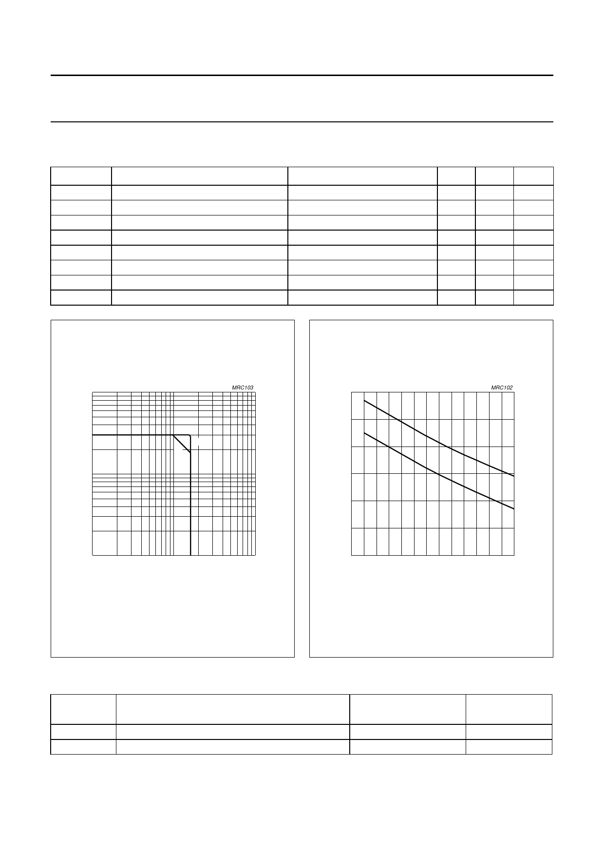
handbook, h1a0lfpage
IC
(A)
1
MRC103
(1)
(2)
handbook, 6h0alfpage
Ptot
(W)
40
20
MRC102
(2)
(1)
10−1
1
10
102
VCE (V)
(1) Tmb = 25 °C.
(2) Th = 70 °C.
Fig.2 DC SOAR.
0
0
20 40 60 80 100 120
Th (oC)
(1) Continuous operation.
(2) Short-time operation during mismatch.
Fig.3 Power/temperature derating curve.
THERMAL RESISTANCE
SYMBOL
PARAMETER
Rth j-mb
Rth mb-h
thermal resistance from junction to mounting base
thermal resistance from mounting base to heatsink
CONDITIONS
Pdis = 46 W; Tmb = 25 °C
THERMAL
RESISTANCE
3.8 K/W
0.4 K/W
January 1993
3
Share Link: 