MX-850MM-QL 데이터 시트보기 (PDF) - DATEL Data Acquisition products
부품명
상세내역
제조사
MX-850MM-QL Datasheet PDF : 4 Pages
| |||
MX-850
Precision, High-Speed 4-Channel Analog Multiplexers
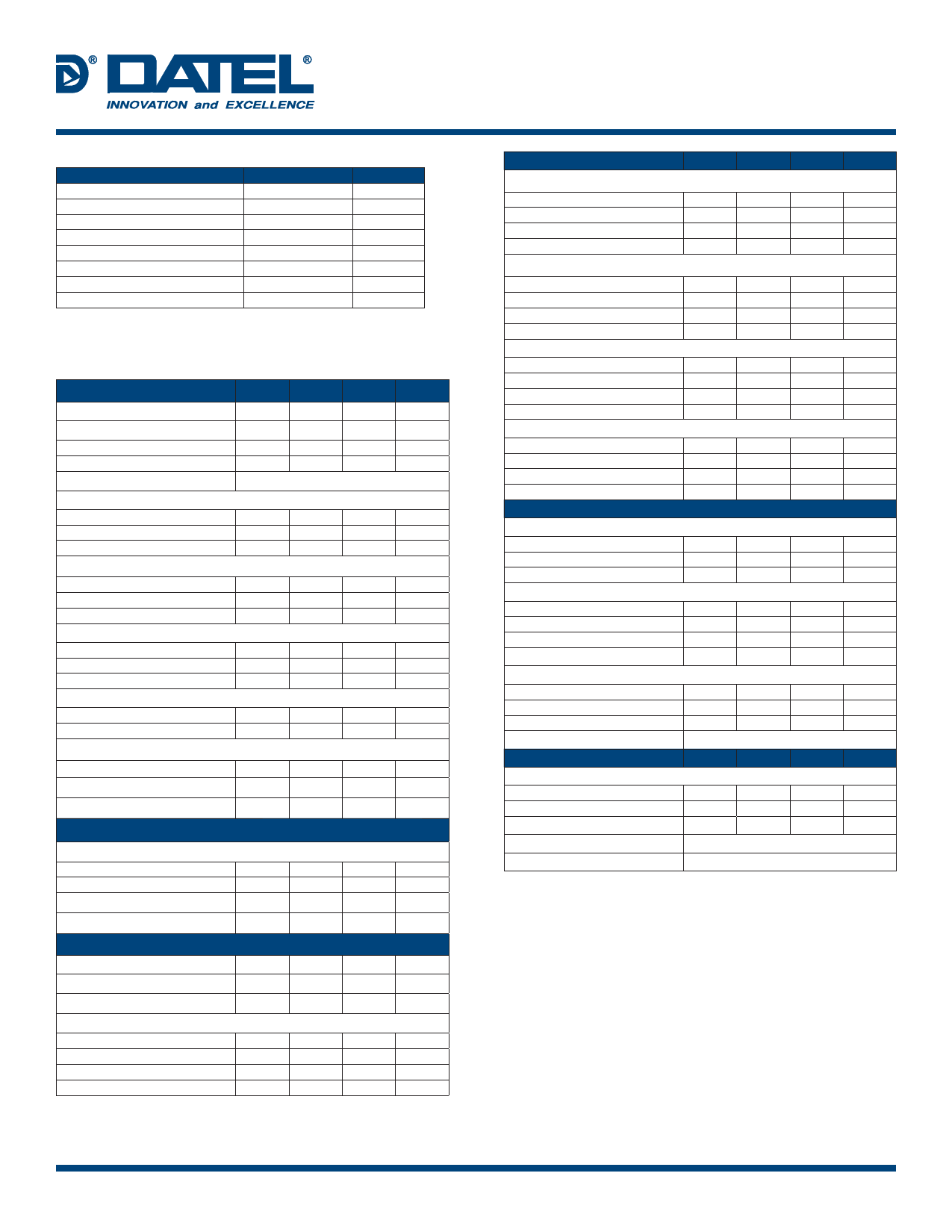
ABSOLUTE MAXIMUM RATINGS
Parameters
+15V Supply, Pin 10
–15V Supply, Pin 14
+5V Supply, Pin 12
Digital Inputs, Pins 1, 2, 3
Analog Inputs, Pins 4, 5, 6, 7
Analog Input Current
Lead temperature (10 seconds)
Switching Frequency/Duty Cycle
Limits
–0.5 to +16.5
+0.5 to –16.5
–0.5 to +7
–0.5 to +6
–10.5 to +10.5
±20
300
10/50
Units
Volts
Volts
Volts
Volts
Volts
mA
°C
MHz/%
FUNCTIONAL SPECIFICATIONS
(Apply over the operating temperature range and over the operating power supply
range unless otherwise specified.)
ANALOG INPUTS
Analog Signal Range
On Resistance, +25°C
0 to +70°C
–55 to +125°C
RON versus VIN
Input Leakage Current (Off)
+25°C
0 to +70°C
–55 to +125°C
Output Leakage Current (Off)
+25°C
0 to +70°C
–55 to +125°C
On Channel Leakage Current
+25°C
0 to +70°C
–55 to +125°C
Channel Input Capacitance
Off
On
Channel Output Capacitance
On
Nonlinearity
Large signal bandwidth (–3dB)
DIGITAL INPUTS
Logic levels
Logic "1"
Logic "0"
Logic Loading "1"
Logic Loading "0"
SWITCHING CHARACTERISTICS
Access Time
Break-Before-Make Delay Time
Enable Delay (On, Off)
Settling Time, 10M Load
10V step to ±0.1%
10V step to ±0.01%
10V step to ±0.003%
10V step to ±0.001%
MIN. TYP. MAX. UNITS
±10
—
—
Volts
—
18
90
Ohms
—
—
120
Ohms
—
—
140
Ohms
See Figure 2.
—
8
50
nA
—
—
0.1
μA
—
—
0.4
μA
—
0.02
0.2
nA
—
—
20
nA
—
—
40
nA
—
10
50
nA
—
—
0.1
μA
—
—
0.4
μA
—
4
6
pF
—
10
12
pF
—
8
10
pF
—
— ±0.001 %FSR
80
100
—
MHz
+2.0
—
—
Volts
—
—
+0.8
Volts
—
—
+10
μA
—
—
–10
μA
—
—
20
ns
—
—
10
ns
—
3
10
ns
—
25
30
ns
—
40
50
ns
—
60
70
ns
—
80
100
ns
SWITCHING CHAR. (cont.)
MIN. TYP. MAX. UNITS
Settling Time, 5k Load
10V step to ±0.1%
10V step to ±0.01%
10V step to ±0.003%
10V step to ±0.001%
—
25
30
ns
—
40
50
ns
—
60
70
ns
—
80
100
ns
Settling Time, 10M Load
20V step to ±0.1%
20V step to ±0.01%
20V step to ±0.003%
20V step to ±0.001%
—
30
35
ns
—
50
60
ns
—
75
85
ns
—
100
120
ns
Settling Time, 5k Load
20V step to ±0.1%
20V step to ±0.01%
20V step to ±0.003%
20V step to ±0.001%
—
30
35
ns
—
50
60
ns
—
75
85
ns
—
100
120
ns
Crosstalk ➀
10kHz (20Vp-p)
1MHz (20Vp-p)
10MHz (5Vp-p)
20MHz (3Vp-p)
—
–105 –100
dB
—
–94
–92
dB
—
–76
–71
dB
—
–64
–62
dB
POWER REQUIREMENTS
Power Supply Range
+15V Supply
–15V Supply
+5V Supply
+14.5 +15 +15.5 Volts
–14.5
–15
–15.5
Volts
+4.75
+5
+5.25 Volts
Power Supply Current, Quiescent
+15V Supply
—
+3
+4
mA
–15V Supply
—
–10
–12
mA
+5V Supply
—
+3
+3.5
mA
Power Supply Rejection Ratio
–80
–90
—
dB
Power Supply Dissipation, Quiescent
+25°C
—
207
270
mW
0 to +70°C
—
—
270
mW
–55 to +125°C
—
—
280
mW
Pd versus Frequency
See Figure 4.
PHYSICAL/ENVIRONMENTAL
Operating Temp. Range, Case
MX-850MC
MX-850MM
Storage Temperature Range
Package Type
Weight
0
—
+70
°C
–55
—
+125
°C
–65
—
+150
°C
14-pin, metal-sealed, ceramic DIP
0.1 ounces (2.8 grams)
➀ See Figures 3a and 3b.
TECHNICAL NOTES
1. Proper operation of the MX-850 multiplexer is dependent upon good board layout
and connection practices. Bypass supplies as shown in the connection diagrams.
Mount bypass capacitors directly to the supply pins whenever possible.
2. All grounds pins (9, 11, 13) should be tied together and connected to ground as
close to the multiplexer as possible.
3. When power is off, current limit input signals on pins 4, 5, 6, and 7 to 20mA.
Failure to current limit can cause permanent damage to the device since, when
powering up or down it is possible that two switches might be on at the same
time. Excessive current (greater than 20mA) will flow from the more positive
input to the more negative input, permanently damaging the device. Applications
in which the power supply for the multiplexer also powers the signal sources
may not require limiting resistors. See Figure 4.
DATEL, Inc. 11 Cabot Boulevard, Mansfield, MA 02048-1151 USA • Tel: (508) 339-3000 • www.datel.com • e-mail: help@datel.com
MDA_MX850.B01 Page 22 of 6
Share Link: 