OPB461 데이터 시트보기 (PDF) - TT Electronics.
부품명
상세내역
제조사
OPB461 Datasheet PDF : 8 Pages
| |||
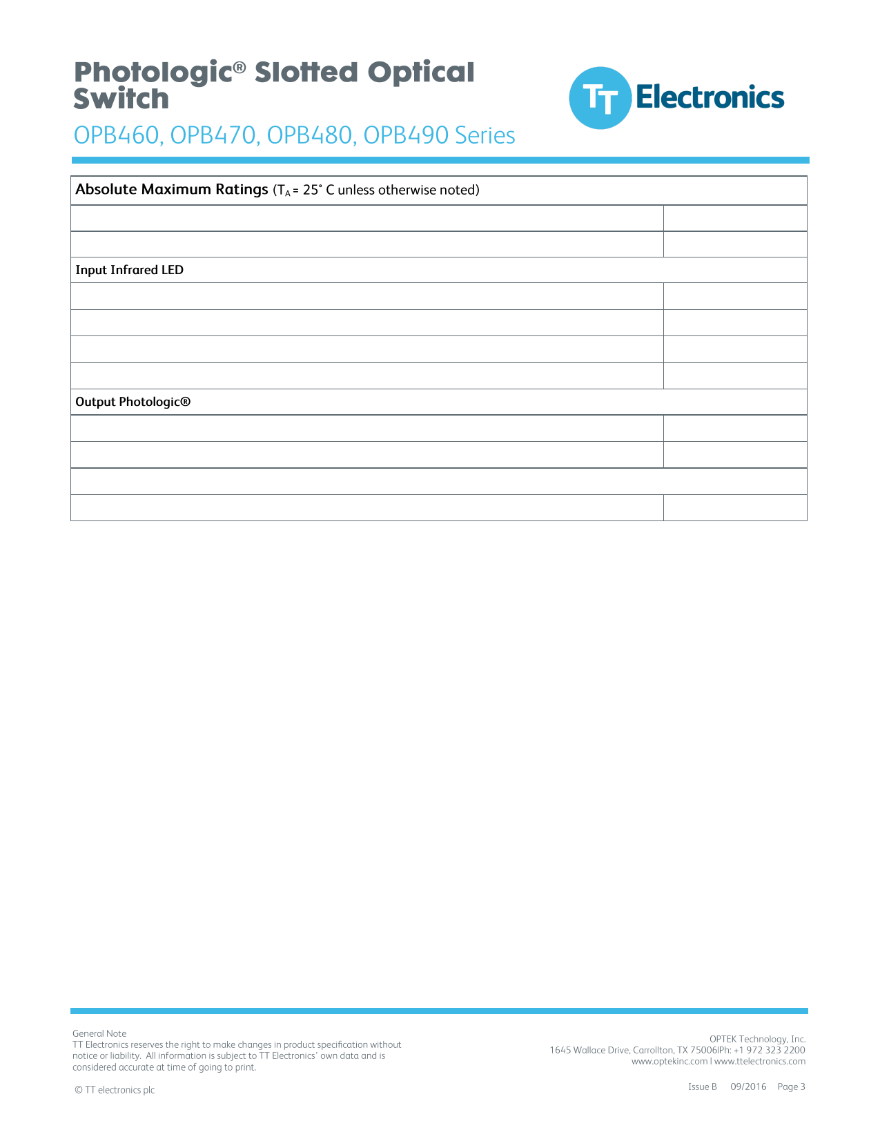
Storage & Operating Temperature Range
Lead Soldering Temperature [1/16 inch (1.6mm) from the case for 5 sec. with soldering iron](1)
-40° C to +85° C
260°C
Supply Voltage, VCC (not to exceed 3 seconds)
Diode Forward DC Current
Diode Reverse DC Voltage
Input Diode Power Dissipation(2)
18 V
40 mA
2V
75 mW
Voltage at Output Lead (Open Collector Output)
Output Photologic® Power Dissipation(3)
25 V
200 mW
Total Device Power Dissipation(4)
275 mW
Notes:
(1) RMA flux is recommended. Duration can be extended to 10 seconds maximum when flow soldering.
(2) Derate linearly 1.67 mW/°C above 25° C (OPB460, OPB470) or derate linearly 1.82 mW/°C above 25° C (OPB480, OPB490).
(3) Derate linearly 1.50 mW/°C above 25° C (OPB460, OPB470) or derate linearly 1.64 mW/°C above 25° C(OPB480, OPB490).
(4) Derate linearly 3.17 mW/°C above 25° C (OPB460, OPB470) or derate linearly 3.45 mW/°C above 25° C (OPB480, OPB490).
(5) The OPB460/OPB470 series are terminated with 0.020” square leads designed for printed circuit board mounting.
(6) The OPB480/OPB490 series of switches are terminated with 24” (609.600 mm) of 7-strand 26 AWG, UL rated insulated wire on each terminal.
Insulation colors and functions are: red (anode), black (cathode), white (VCC,), blue (output) and green (ground). Other wire lengths and/or
colors in addition to customer selected connectors are available. Contact your local representative or call the factory.
Share Link: 