STA020DJTR 데이터 시트보기 (PDF) - STMicroelectronics
부품명
상세내역
제조사
STA020DJTR Datasheet PDF : 15 Pages
| |||
STA020
General description
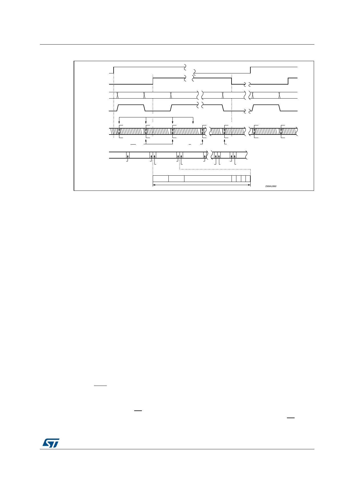
Figure 6. CBL and transmitter timing
TRNPT high
CBL
TRNPT low
SDATA
LEFT 0
RIGHT 0
LEFT 1
LEFT 128
RIGHT 128
LEFT 0
RIGHT 0
FSYNC
C BITS FROM CPIN
TRNPT high
C,U,V
TRNPT low
CUV0L
CUV191R
CUV0R
CUV0L
CUV1L
CUV0R
CUV1R
CUV1L
CUV128R
CUV128L
C BITS OR'ed
w/PRO pin
C BITS OR'ed
w/C1 pin
BITS 0 of C.S.
BLOCK BYTE 16
TXP
TXN
Preamble Y
RIGHT 191
VUCP191R
LEFT 0
VUCP0L
Preamble Z
RIGHT 0
LEFT
128
RIGHT
128
VUCP0R
Preamble Y VUCP127R
VUCP128L
Preamble X Preamble Y
bit 0
34
78
Preamble Z Aux Data LSB
Left 0 - Audio Data
27 28 29 30 31
MSB V0 U0 C0 P0
SUB-FRAME
CUV0L
CUV191R
D99AU990
CUV0R
CUV0L
2.5
Transparent mode
In certain applications it is desirable to receive digital audio data with the STA120 and
retransmit it with the STA020. In this case, channel status, user and validity information
must pass through unaltered. For studio environments, AES recommends that signal timing
synchronization be maintained throughout the studio. Frame synchronization of digital audio
signals input to and output from a piece of equipment must be within ±5%.
The transparent mode of the STA020 is selected by setting TRNPT, pin 24, high. In this
mode, the CBL pin becomes an input, allowing direct connection of the outputs of the
STA120 to the inputs of the STA020 as shown in Figure 7. The transmitter and receiver are
synchronized by the FSYNC signal. CBL specifies the start of a new channel status block
boundary, allowing the transmit block structure to be slaved to the block structure of the
receiver.
In the transparent mode, C, U and V are now transmitted with the current audio sample as
shown in Figure 7 (TRNPT high) and the dedicated channel status pins are ignored.
When FSYNC is a word clock (Format 2), CBL is sampled when left C, U, V are sampled.
When FSYNC is Left/Right, CBL is sampled when left C, U, V are sampled. The channel
status block boundary is reset when CBL transitions from low to high (based on two
successive samples of CBL). MCK for the STA020 is normally expected to be 128 times the
sample frequency, in the transparent mode MCK must be 256 Fs.
2.6
Professional mode
Setting PRO low places the STA020 in professional mode as shown in Figure 8. In
professional mode, channel status bit 0 is transmitted as a one and bits 1, 2, 3, 4, 6, 7 and 9
can be controlled via dedicated pins. The pins are actually the inverse of the identified bit.
For example, tying the C1 pin low places a one in channel status bit 1. As shown in the
application note, “Overview of AES/EBU Digital Audio Interface Data Structures”, C1
DocID006832 Rev 7
9/15
15
Share Link: 