BU1425AK View Datasheet(PDF) - ROHM Semiconductor
Part Name
Description
Manufacturer
BU1425AK Datasheet PDF : 32 Pages
| |||
Multimedia ICs
BU1425AK / BU1425AKV
∗ Reversal of the U and V timing using the H / L state of TEST[2] can be controlled regardless of whether CLKSW is
HIGH or LOW (the input clock is a doubled clock or not).
∗ When using the RGB input mode, TEST[2] should be fixed at LOW.
∗ In the Master mode, HSYNC is output at the timing shown in Fig. 26. For that reason, the timing of U and V should
be determined by counting from that falling edge. In the Slave mode, the HSY, U, and V data should be input at the
timing shown in Fig. 26.
Table 20
TEST2
(pin26)
0
0
1
1
CLKSW
(pin53)
0
1
0
1
In a doubled clock mode, the timing of U and V is as shown in Fig. 7-1.
In a regular clock mode, the timing of U and V is as shown in Fig. 7-1.
In a doubled clock mode, the timing of U and V is as shown in Fig. 7-2.
In a regular clock mode, the timing of U and V is as shown in Fig. 7-2.
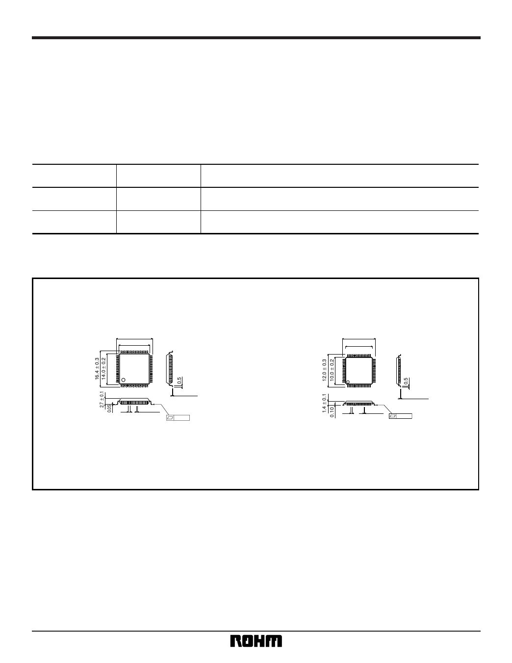
•External dimensions (Units: mm)
BU1425AK
BU1425AKV
16.4 ± 0.3
14.0 ± 0.2
48
33
49
32
64
1
17
16
0.8 0.35 ± 0.1
0.15 ± 0.1
0.15
12.0 ± 0.3
10.0 ± 0.2
48
33
49
32
64
1
0.5
17
16
0.2 ± 0.1
0.125 ± 0.1
0.1
QFP-A64
VQFP64
32
Share Link: 