MM1394 View Datasheet(PDF) - Mitsumi
Part Name
Description
Manufacturer
MM1394 Datasheet PDF : 11 Pages
| |||
MITSUMI
NTSC/PAL Encoder MM1394
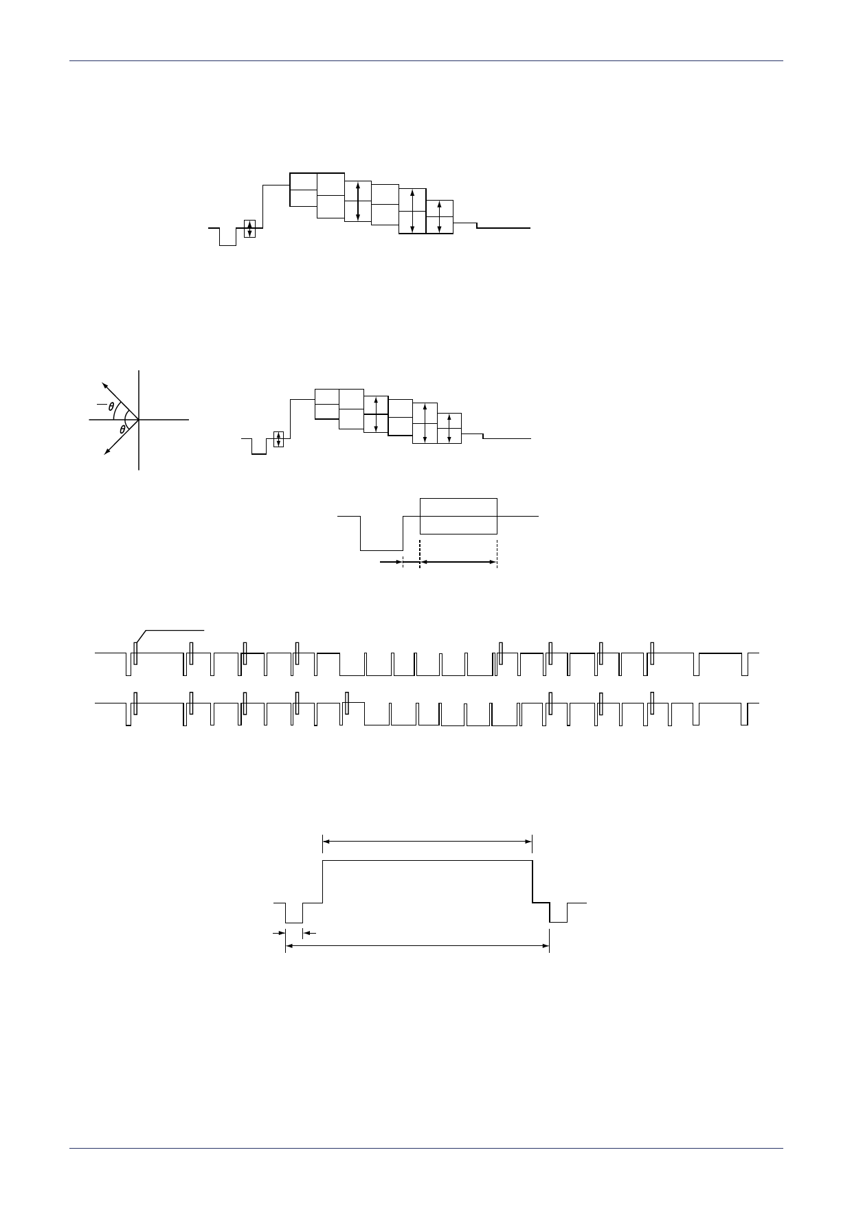
* Note 4 : 4 Chroma signal measurement (NTSC mode)
Chroma level ratio is the ratio between each color signal level and burst signal level.
Each color phase is 180° from burst signal phase (given B-Y axis as 0°).
CL (b)
CL (g)
CL (r)
CL (bu)
CL(r)
CL(R)= —C—L—(b—)
CL(R)= —C—L—(g—)
CL(b)
CL(R)= —CC—LL(—(bbu—))
* Note 5 : 5 Chroma signal measurement (PAL mode)
Assume burst 135° side signal as color-1, and burst 225° side signal as color-2.
Phase measurement is done assuming the middle of burst-1 and burst-2 phase as 180° (given B-
Y axis as 0°).
R-Y axis
Burst-1
1
2
B-Y axis CL (b)
CL (g)
CL (r)
CL (bu)
CL(R)= —C—L—(r—)
CL(b)
CL(R)= —CC—LL((—gb—))
CL(bu)
CL(R)= —C—L(—b—)
Burst-2
* Note 6 : 6 Burst signal
VIDEO OUT
td
tw
* Note 7 : 7 3.58MHz component level for RGB input no signal.
Burst
EVEN
ODD
* Note 8 : 8 Input dynamic range measurement
Input the signal shown below and measure video output sync level. Sync level between
0.26~0.33V is acceptable.
SG10
52.15µS
0.829V
(1161RE)
4.88µS
63.56µS
-0.286V
Share Link: 