LF2250QC20 View Datasheet(PDF) - LOGIC Devices
Part Name
Description
Manufacturer
LF2250QC20 Datasheet PDF : 15 Pages
| |||
DEVICES INCORPORATED
LF2250
12 x 10-bit Matrix Multiplier
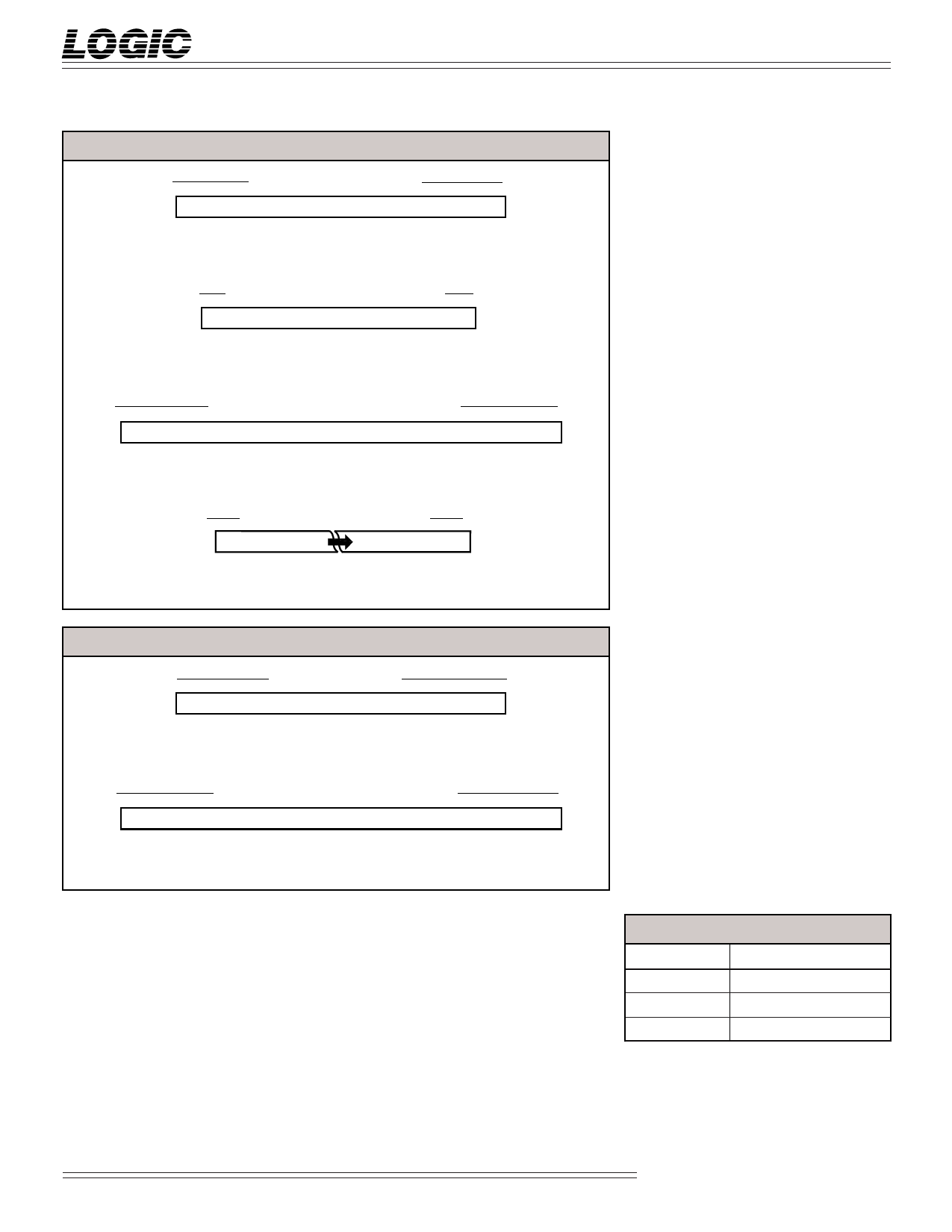
FIGURE 1A. INPUT FORMATS
Data Input (All Modes)
11 10 9 8 7 6 5 4 3 2 1 0
–211 210 29 28 27 26 25 24 23 22 21 20
(Sign)
Coefficient Input (All Modes)
98765 43210
–20 2–1 2–2 2–3 2–4 2–5 2–6 2–7 2–8 2–9
(Sign)
Cascade Input (Modes 01, 10, 11)
15 14 13 12 11 10 9 8 7 6 5 4 3 2 1 0
–211 210 29 28 27 26 25 24 23 22 21 20 2–1 2–2 2–3 2–4
(Sign)
Internal Sum (All Modes)
20 19 18 17
–211 210 29 28
(Sign)
3210
2–6 2–7 2–8 2–9
FIGURE 1B. OUTPUT FORMATS
Result (Mode 00)
11 10 9 8 7 6 5 4 3 2 1 0
–211 210 29 28 27 26 25 24 23 22 21 20
(Sign)
Cascade Out (Modes 01, 10, 11)
15 14 13 12 11 10 9 8 7 6 5 4 3 2 1 0
–211 210 29 28 27 26 25 24 23 22 21 20 2–1 2–2 2–3 2–4
(Sign)
CASOUT15-0 — Cascade Output
In the filter modes (Modes 01, 10, 11),
the 12-bit Z port and four bits of the Y
port are internally reconfigured as the
16-bit registered cascade output port.
NOTE: The X, Y, and Z ports are
automatically reconfigured by the LF2250
as the cascade-in and cascade-out ports as
required for each operating mode.
Because both the X and Z ports are used
for the cascade ports, all X port pins and
all Z port pins are labelled as XC and
ZC, respectively. All Y port pins that are
used for the cascade ports are labelled as
YC. Those Y port pins which are not
used for the cascade ports are labelled as
Y.
Controls
MODE1-0 — Mode Select
The registered mode select inputs
determine the operating mode of the
LF2250 (Table 1) for data being input
on the next clock cycle. When switch-
ing between modes, the internal
pipeline latencies of the device must
be observed. After switching operat-
ing modes, the user must allow
enough clock cycles to pass to flush
the internal registers before valid data
will appear on the outputs.
CWE1-0 — Coefficient Write Enable
The registered coefficient write enable
inputs determine which internal
coefficient register set to update
(Table 4) on the next clock cycle.
CASIN15-0 — Cascade Input
In the filter modes (Modes 01, 10, 11),
the 12-bit X port and four bits of the Y
port are internally reconfigured as the
16-bit registered cascade input port.
Data presented to this port will be
added to the internal sum of prod-
ucts.
Outputs
X11-0, Y11-0, Z11-0 — Data Outputs
X, Y, and Z are the 12-bit registered
output ports for the matrix multiply
mode (Mode 00). These ports are
automatically reconfigured for the
filter modes (Modes 01, 10, 11) as the
cascade-in and cascade-out ports.
TABLE 3. COEFFICIENT INPUTS
INPUT PORT
KA
KB
KC
REG. AVAILABLE
KA1, KA2, KA3
KB1, KB2, KB3
KC1, KC2, KC3
Video Imaging Products
3
08/16/2000–LDS.2250-L
Share Link: 