SAA4990H View Datasheet(PDF) - Philips Electronics
Part Name
Description
Manufacturer
SAA4990H Datasheet PDF : 28 Pages
| |||
Philips Semiconductors
Progressive scan-Zoom and Noise
reduction IC (PROZONIC)
Preliminary specification
SAA4990H
Vertical sample rate conversion
The variable vertical sample rate conversion is performed
on top of the noise reduced and progressively scanned
data.
The vertical sample rate conversion is intended to cope
with the various letter box formats, to be displayed on
displays with e.g. 16:9 aspect ratio. For this sample rate
conversion, which usually has both a vertical and a
horizontal component, the vertical sample rate conversion
is taken care of in the PROZONIC, while the horizontal
compression can be done in e.g. TDA8753A or
SAA4995WP.
The vertical sample rate conversion can also be used to
convert from an NTSC 525 lines source to a 625 line
display, by setting a vertical sample rate conversion factor
of 6⁄5 and necessarily some line-time reduction.
Conversion from 625 to 525 lines is possible with
progressive scan output, by setting a vertical sample rate
conversion of 5⁄6.
The principle of vertical sample rate conversion is based
on linear interpolation from two successive lines of video in
a frame to produce an output line in either a field or a
frame.
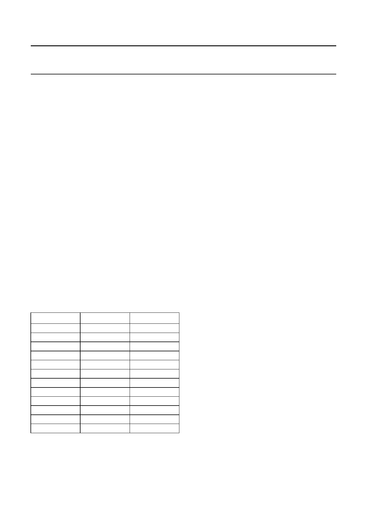
The vertical sample rate conversion factor can be switched
to the following settings for increasing the number of
output lines w.r.t. the number of input lines; see Table 1.
Table 1 Vertical sample rate conversion factor
INPUT LINES
2
14
12
10
8
6
10
4
10
6
8
2
OUTPUT LINES
2
16
14
12
10
8
14
6
16
10
14
4
FACTOR
1.00
1.14
1.16
1.20
1.25
1.33
1.40
1.50
1.60
1.67
1.75
2.00
Movie phase detection
While processing video, that was originally film
(25 movement phases per second in the case of 50 Hz
field rates), median filtering is not needed when fields are
combined that have the same movement phase. As this
phase is not generally known, the PROZONIC has a
detection circuit to help determine it. The detection is
based on measurement of absolute luminance differences
between successive input fields, pixel by pixel. These
differences are summed over all active video and give a
number every field. In case of video from film with sufficient
movement, the measured number will alternately be HIGH
and LOW. With the controlling microcontroller, this data
can be filtered appropriately to switch to movie processing
in the correct phase.
The PROZONIC has a provision to generate a rectangular
box, which is position and size programmable. This box
can be used to enable the measurement in the movie
phase detection circuit, only within this rectangle.
Otherwise, the active video part in a field is marked with a
derivative of the RE pulse.
Box generation
A rectangular box is defined by the coordinates of the
left-upper edge (hor_start_box, vert_start_box) and the
right-lower edge (hor_stop_box, vert_stop_box). The
reference for the coordinates are the HD positive edge
(with some processing delay) for the horizontal direction
and the VD positive edge for the vertical.
The box can serve the following purposes:
• Switch between adaptive and fixed k in noise reduction.
If k-fixed is set to 0, then the box switches between
adaptive noise reduced and fully still picture areas. This
provides an option for producing multi picture (still)
images. If no noise reduction is desired in the area
where NR is adaptive, the adaptive setting can be
programmed with k steps to all zeros.
• Switch the movie phase detect measurement to a
defined area of the video.
Decreasing the number of lines on the display w.r.t. the
number of input lines is only possible with progressive
scan output.
1996 Oct 25
10
Share Link: 