HFBR-5527 View Datasheet(PDF) - HP => Agilent Technologies
Part Name
Description
Manufacturer
HFBR-5527 Datasheet PDF : 12 Pages
| |||
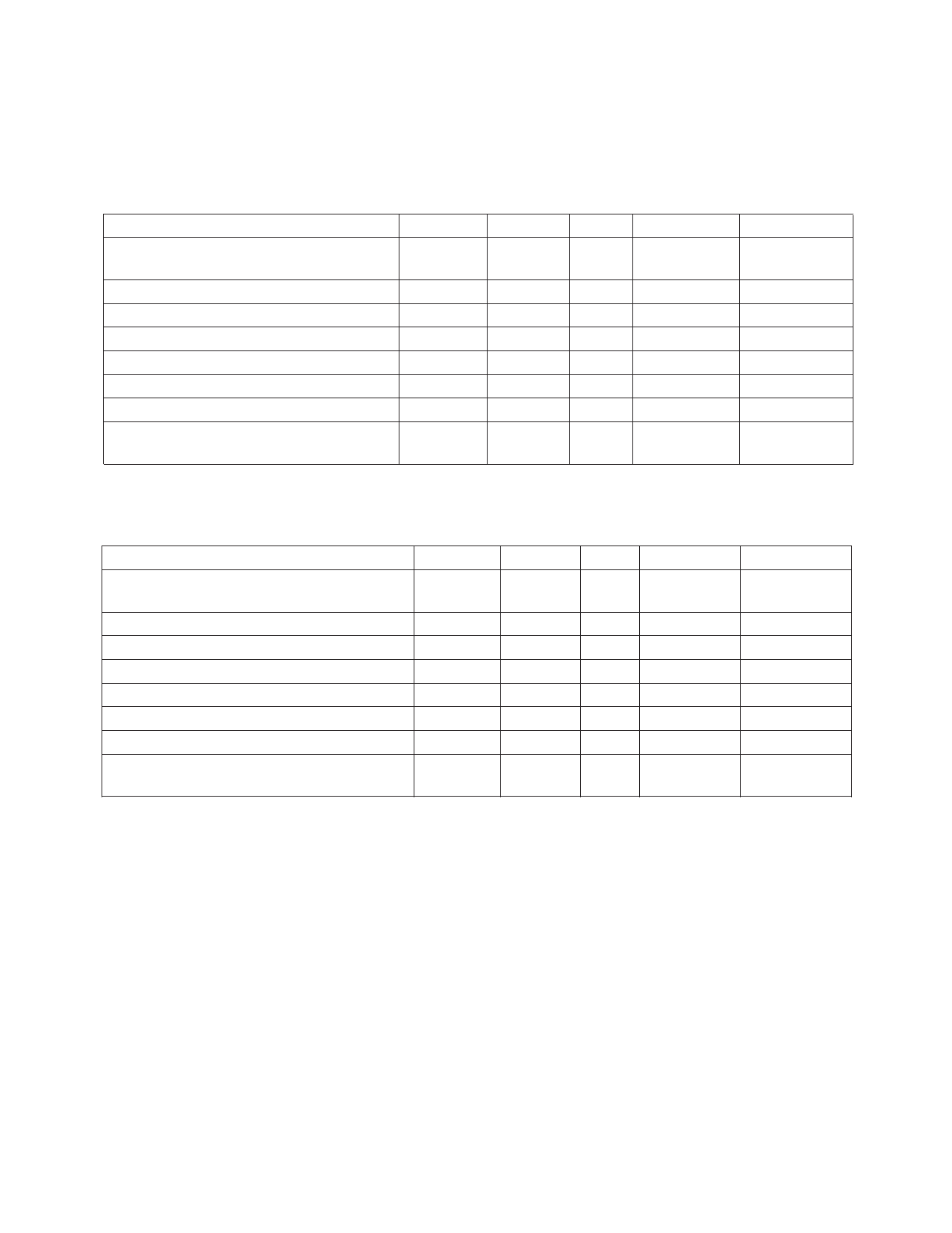
Plastic Optical Fiber (1 mm POF) Transmitter Application Circuit:
Performance of the transmitter in the recommended application circuit (Figure 1) for POF; 1-125 MBd, 25°C.
Parameter
Symbol Typical Unit Condition
Note
Average Optical Power 1 mm POF
Pavg
-9.7
dBm 50% Duty Note 1, Fig. 3
Cycle
Average Modulated Power 1 mm POF
Optical Rise Time (10% to 90%)
Optical Fall Time (90% to 10%)
High Level LED Current (On)
Low Level LED Current (Off)
Optical Overshoot - 1 mm POF
Pmod
tr
tf
IF,H
IF,L
-11.3
2.1
2.8
30
3
45
dBm
ns
ns
mA
mA
%
5 MHz
5 MHz
Note 2, Fig. 3
Note 3
Note 3
Transmitter Application Circuit
Current Consumption - 1 mm POF
ICC
115
mA
Figure 1
Hard Clad Silica Fiber (200 µm HCS) Transmitter Application Circuit: Performance of
the transmitter in the recommended application circuit (Figure 1) for HCS; 1-125 MBd, 25°C.
Parameter
Average Optical Power 200 µm HCS
Average Modulated Power 200 µm HCS
Optical Rise Time (10% to 90%)
Optical Fall Time (90% to 10%)
High Level LED Current (On)
Low Level LED Current (Off)
Optical Overshoot - 200 µm HCS
Transmitter Application Circuit
Current Consumption - 200 µm HCS
Symbol
Pavg
Pmod
tr
tf
IF,H
IF,L
ICC
Typical
-14.6
-16.2
3.1
3.4
60
6
30
130
Unit
dBm
dBm
ns
ns
mA
mA
%
mA
Condition
50% Duty
Cycle
5 MHz
5 MHz
Note
Note 1, Fig. 3
Note 2, Fig. 3
Note 3
Note 3
Figure 1
Notes:
1. Average optical power is measured with an average power meter at 50% duty cycle, after 1 meter of fiber.
2. To allow the LED to switch at high speeds, the recommended drive circuit modulates LED light output between two non-zero power
levels. The modulated (useful) power is the difference between the high and low level of light output power (transmitted) or input
power (received), which can be measured with an average power meter as a function of duty cycle (see Figure 3). Average Modulated
Power is defined as one half the slope of the average power versus duty cycle:
Average Modulated Power = ––[—Pa—vg—@—8—0%—d—ut—y —cy—cle—- —Pa—vg —@—20—%—d—uty—c—yc—le—]
(2) [0.80 - 0.20]
3. High and low level LED currents refer to the current through the LED. The low level LED “off” current, sometimes referred to as
“hold-on” current, is prebias supplied to the LED during the off state to facilitate fast switching speeds.
167
Share Link: 