ADM1021AARQ View Datasheet(PDF) - Analog Devices
Part Name
Description
Manufacturer
ADM1021AARQ Datasheet PDF : 16 Pages
| |||
ADM1021A
4
100
80
3
60
10mV p-p
2
40
20
1
0
0
100k
1M
10M
100M
1G
FREQUENCY – Hz
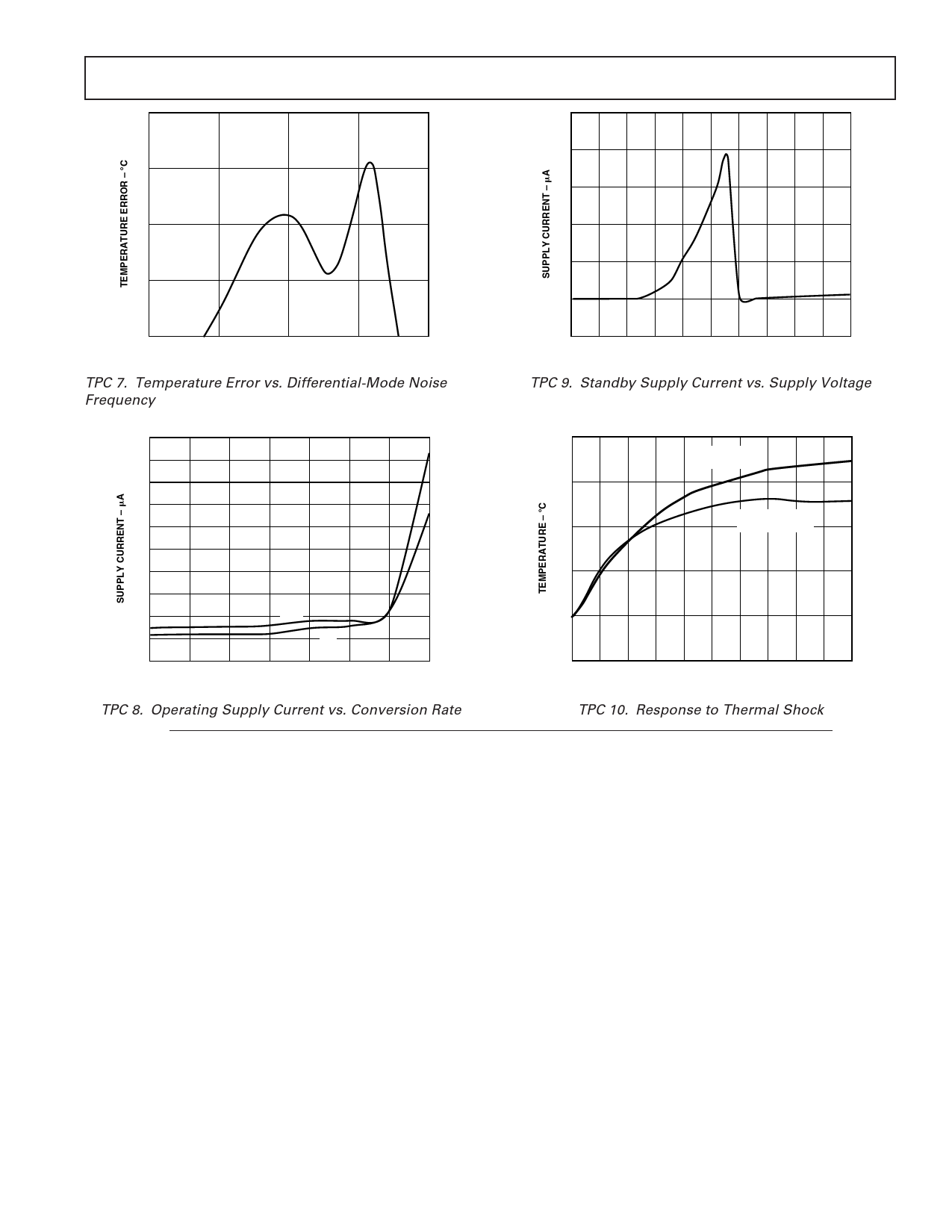
TPC 7. Temperature Error vs. Differential-Mode Noise
Frequency
–20
0
0.5 1.0 1.5 2.0 2.5 3.0 3.5 4.0 4.5 5.0
SUPPLY VOLTAGE – V
TPC 9. Standby Supply Current vs. Supply Voltage
550
500
450
400
350
300
250
200
150
3.3V
100
5V
50
0.0625 0.125 0.25 0.5
1
2
4
8
CONVERSION RATE – Hz
TPC 8. Operating Supply Current vs. Conversion Rate
125
REMOTE
TEMPERATURE
100
INT
75
TEMPERATURE
50
25
0
0
12
3
4
5
6
78
9 10
TIME – Seconds
TPC 10. Response to Thermal Shock
FUNCTIONAL DESCRIPTION
The ADM1021A contains a two-channel A-to-D converter with
special input-signal conditioning to enable operation with remote and
on-chip diode temperature sensors. When the ADM1021A is operat-
ing normally, the A-to-D converter operates in a free-running mode.
The analog input multiplexer alternately selects either the on-chip
temperature sensor to measure its local temperature, or the remote
temperature sensor. These signals are digitized by the ADC and
the results stored in the Local and Remote Temperature Value
Registers as 8-bit, twos complement words.
The measurement results are compared with local and remote,
high and low temperature limits, stored in four on-chip registers.
Out-of-limit comparisons generate flags that are stored in the
status register, and one or more out-of-limit results will cause
the ALERT output to pull low.
The limit registers can be programmed, and the device con-
trolled and configured, via the serial System Management Bus.
The contents of any register can also be read back via the SMBus.
Control and configuration functions consist of:
• Switching the device between normal operation and standby
mode.
• Masking or enabling the ALERT output.
• Selecting the conversion rate.
On initial power-up, the remote and local temperature values
default to –128°C. Since the device normally powers up converting,
a measurement of local and remote temperature is made and these
values are then stored before a comparison with the stored limits
is made. However, if the part is powered up in standby mode
(STBY pin pulled low), no new values are written to the register
before a comparison is made. As a result, both RLOW and LLOW
are tripped in the Status Register, thus generating an ALERT out-
put. This may be cleared in one of two ways:
1. Change both the local and remote lower limits to –128°C
and read the status register (which in turn clears the ALERT
output).
2. Take the part out of standby and read the status register
(which in turn clears the ALERT output). This will work only
if the measured values are within the limit values.
MEASUREMENT METHOD
A simple method of measuring temperature is to exploit the
negative temperature coefficient of a diode, or the base-emitter
voltage of a transistor, operated at constant current. Unfortu-
nately, this technique requires calibration to null out the effect
of the absolute value of VBE, which varies from device to device.
REV. D
–5–
Share Link: 