ADM1021AARQ View Datasheet(PDF) - Analog Devices
Part Name
Description
Manufacturer
ADM1021AARQ Datasheet PDF : 16 Pages
| |||
ADM1021A
VDD
I
N؋I
IBIAS
REMOTE
SENSING
TRANSISTOR
D+
C1*
D–
BIAS
DIODE
LOWPASS FILTER
fC = 65kHz
VOUT+
TO ADC
VOUT–
*CAPACITOR C1 IS OPTIONAL. IT IS ONLY NECESSARY IN NOISY ENVIRONMENTS.
C1 = 2.2nF TYPICAL, 3nF MAX.
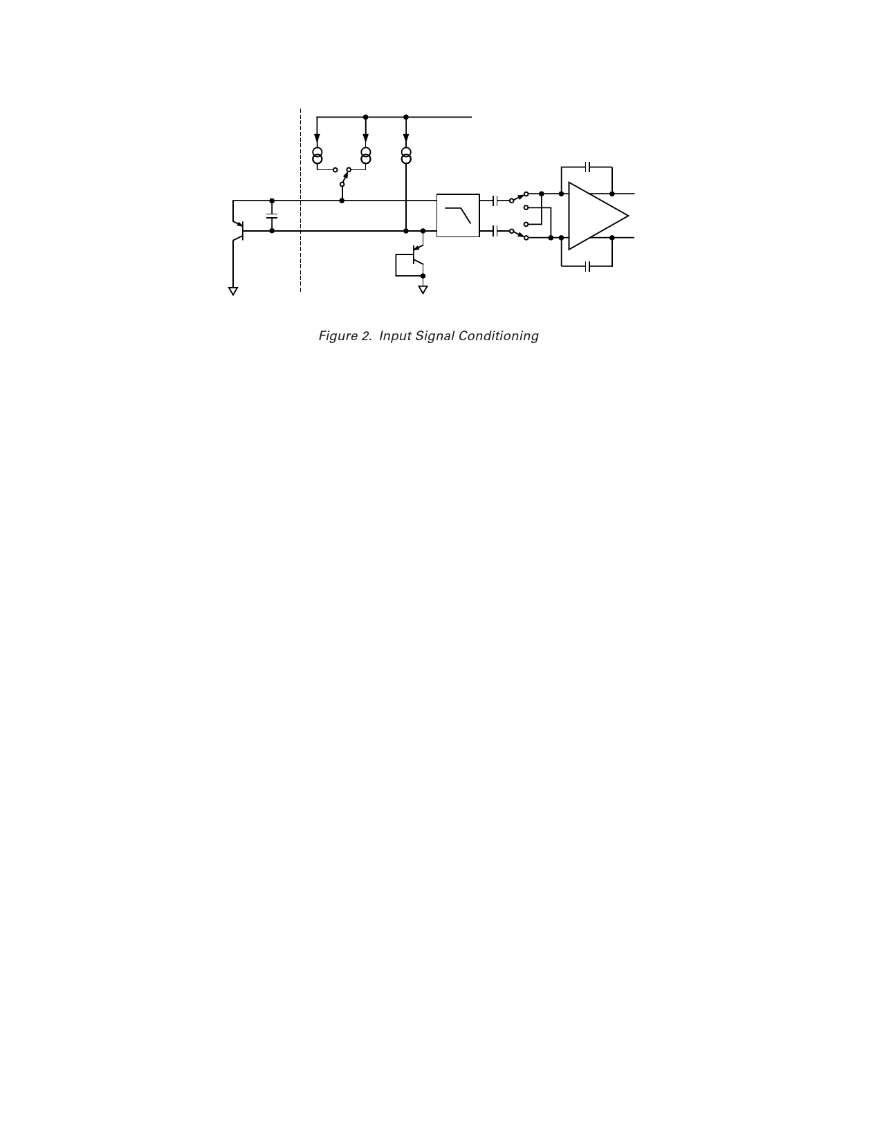
Figure 2. Input Signal Conditioning
The technique used in the ADM1021A is to measure the change
in VBE when the device is operated at two different currents.
This is given by:
where:
∆VBE = KT/q × ln(N)
K is Boltzmann’s constant,
q is charge on the electron (1.6 × 10⁻¹⁹ coulombs),
T is absolute temperature in kelvins,
N is ratio of the two currents.
Figure 2 shows the input signal conditioning used to measure the
output of an external temperature sensor. This figure shows the
external sensor as a substrate transistor, provided for tempera-
ture monitoring on some microprocessors, but it could equally
well be a discrete transistor. If a discrete transistor is used, the
collector will not be grounded and should be linked to the base.
To prevent ground noise interfering with the measurement, the
more negative terminal of the sensor is not referenced to ground,
but is biased above ground by an internal diode at the D– input.
If the sensor is operating in a noisy environment, C1 may optionally
be added as a noise filter. Its value is typically 2200 pF, but should
be no more than 3000 pF. See the section on layout considerations
for more information on C1.
To measure ∆VBE, the sensor is switched between operating currents
of I and N × I. The resulting waveform is passed through a 65 kHz
low-pass filter to remove noise, then to a chopper-stabilized ampli-
fier that performs the functions of amplification and rectification of
the waveform to produce a dc voltage proportional to ∆VBE. This
voltage is measured by the ADC to give a temperature output in
8-bit twos complement format. To reduce the effects of noise
further, digital filtering is performed by averaging the results of
16 measurement cycles.
Signal conditioning and measurement of the internal tempera-
ture sensor is performed in a similar manner.
DIFFERENCES BETWEEN THE ADM1021 AND THE
ADM1021A
Although the ADM1021A is pin-for-pin compatible with the
ADM1021, there are some differences between the two devices.
Below is a summary of these differences and reasons for the changes.
1. The ADM1021A forces a larger current through the remote
temperature sensing diode, typically 205 µA versus 90 µA
for the ADM1021. The main reason for this is to improve
the noise immunity of the part.
2. As a result of the greater Remote Sensor Source Current the
operating current of the ADM1021A is higher than that of
the ADM1021, typically 205 mA versus 160 mA.
3. The temperature measurement range of the ADM1021A is
0°C to 127°C, compared with –128°C to +127°C for the
ADM1021. As a result, the ADM1021 should be used if
negative temperature measurement is required.
4. The power-on reset values of the remote and local tempera-
ture values are –128°C in the ADM1021A as compared with
0°C in the ADM1021. As the part is powered up converting
(except when the part is in standby mode, i.e., Pin 15 is
pulled low) the part will measure the actual values of remote
and local temperature and write these to the registers.
5. The four MSBs of the Revision Register may be used to
identify the part. The ADM1021 Revision Register reads
0xh and the ADM1021A reads 3xh.
6. The power-on default value of the Address Pointer Register
is undefined in the ADM1021A and is equal to 00h in the
ADM1021. As a result, a value must be written to the Address
Pointer Register before a read is done in the ADM1021A.
The ADM1021 is capable of reading back local temperature
without writing to the Address Pointer Register as it defaulted
to the local temperature measurement register at power-up.
7. Setting the mask bit (Bit 7 Config Reg) on the ADM1021A
will mask current and future ALERTs. On the ADM1021
the mask bit will only mask future ALERTs. Any current
ALERT will have to be cleared using an ARA.
TEMPERATURE DATA FORMAT
One LSB of the ADC corresponds to 1°C, so the ADC can theo-
retically measure from –128°C to +127°C, although the device
does not measure temperatures below 0°C so the actual range is
0°C to 127°C. The temperature data format is shown in Table I.
The results of the local and remote temperature measurements
are stored in the local and remote temperature value registers,
and are compared with limits programmed into the local and
remote high and low limit registers.
–6–
REV. D
Share Link: 