UT1553RTMP View Datasheet(PDF) - Aeroflex UTMC
Part Name
Description
Manufacturer
UT1553RTMP Datasheet PDF : 40 Pages
| |||
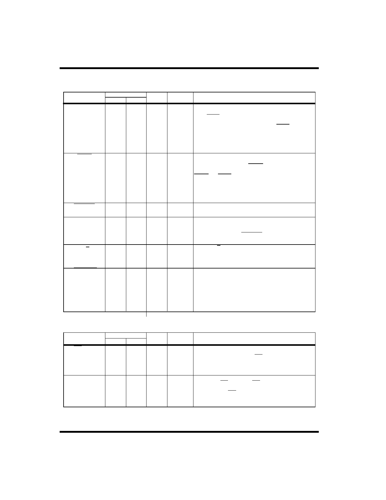
STATUS SIGNALS
NAME
EORT
PIN NUMBER
LCC PGA
36 J11
TYPE ACTIVE
DESCRIPTION
TTO AL End of Receive/Transmit. This interrupt is a pulse that is
maskable by writing to the Control Register. The user can
select EORTto occur at the end of receive command activity,
at the end of transmit command activity, under either of these
conditions, or disable it completely. The EORT output is de-
signed to simulate an open-collector output and requires a
pull-up resistor. (250ns pulse width). This signal is not gen-
erated if a message error condition exists.
EOMC
37 H10
TTO AL End of Mode Code. this non-maskable interrupt is a pulse that
occurs at the end of all memory accesses associated with any
mode code command. The EOMC output is designed to sim-
ulate an open-collector output and requires a pull-up resistor.
EOMC and EORT can be logically ORed together to form a
composite interrupt. The 250ns pulse width is generated after
command word is stored. This signal is not generated if a
message error condition exists.
COMSTR
MERR
38 H11
TO
AL Command Strobe. This low-going pulse identifies re-
ceipt of a valid 1553 command word.
39 G9
TO
AH Message Error. Active when the RTMP detects an error in
the 1553 transmission and sets the Message Error bit in the
status word. MERR is reset when the RTMP receives the next
valid command word. (COMSTR assertion)
CHA/ B
28 K8 TO
-- Channel A/B. When high, this output indicates the RTMP
received the last command on Channel A; when low, the last
command was received on Channel B.
TIMERON
29
L9
TO
AL Timer On. Indicates the RTMP is transmitting data.
The output remains active until the data transmission is
complete or the internal fail-safe timer times out (600ms
for 1553A and 800ms for 1553B). The RTMP internally
disables both transmitters and keeps them disabled until the
RTMP receives a valid command word. This signal is as-
serted approximately 250ns
before beginning of status word transmission.
MODE CODE/SUBADDRESS
NAME
MC/SA
PIN NUMBER
LCC PGA
21
J5
TYPE
TTO
MCSA0
MCSA1
MCSA2
MCSA3
MCSA4
15
L3
TTO
16
K4
17
L4
18
K6
19
K5
ACTIVE
DESCRIPTION
AL Mode Code/Subaddress. MC/SA = 0 indicates that the MC-
SAO-MCSA4 pins contain the Mode Code bits of the most
recently received mode code. MC /SA = 1 indicates that
MCSA0-MCSA4 pins contain the Subaddress bits of the
most recently received command word.
-- Mode Code/Subaddress. These five bits are used in conjunc-
tion with the M C/SA output. MC /SA = 0 indicates that these
five bits are the five least significant bits of the mode code
command word. MC /SA = 1 indicates these five bits are the
1553 command word subaddress.
RTMP-9
Share Link: 